


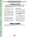

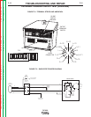


FIRING BOARD
G3742-[ ]
LED7
LED8
LED9
LED1
LED2
LED3
LED4
LED5
LED6
LED10
J5
J6
J7
J4
J8
(205) 8
(206) 7
(207) 6
(208) 5
4
3
2
1
16 (204)
15 (203)
14
13 (231)
12 (215)
11
10
9
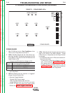
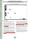
FIGURE F.1 – FIRING BOARD LEDs
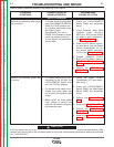
PC BOARD TROUBLESHOOTING GUIDE (continued)
FIRING BOARD
1. With DC-600 set for the Test Conditions all ten
LEDs on the Firing Board should be lit.
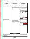
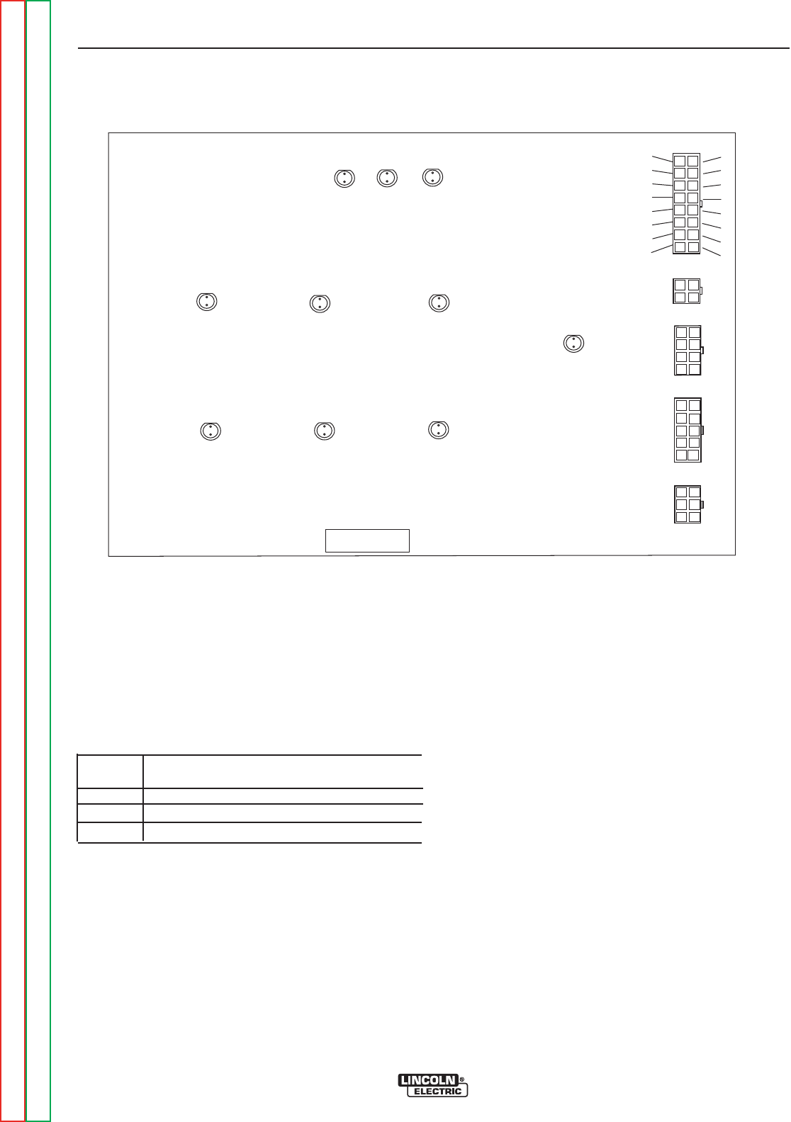
2. LEDs 7, 8 & 9 indicate that the three 34vac sup-
plies from the Main Transformer are present on the
Firing Board. They should all be ON whenever the
Power Switch is ON.
• If any are not ON check the voltages at P5
• If voltage is present and the LED is OFF, replace
the Firing Board
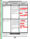
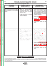
3. LED 10 indicates that the machine is “triggered”
(Output Terminal Switch ON).
• Alternate Trigger Methods:
Operate Wire Feeder trigger.
Place a jumper across 2 & 4 on T.S.2.
Jumper between pins C & D of 14 pin connector.
• If LED 10 does not come ON, check wiring.
Perform the Internal Trigger Circuit Test.
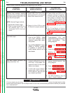
4. LEDs 1 thru 6 indicate that gate signals are being
sent to the SCRs in the Main Rectifier. These
LEDs will vary in brightness as the Output Control
is changed.
• It is important that all six LEDs are the same bril-
liance as each other.
If none are lit, check the voltage at lead 231
(P5 - Pin13). See the Control Board Test.If
OK, Replace the Firing Board.
If LEDs are not the same brilliance, see the
SCR Bridge Test and check the connections
to J-4. If OK, replace the Firing Board.
TROUBLESHOOTING AND REPAIR
F-10 F-10
DC-600
Return to Section TOC Return to Section TOC Return to Section TOC Return to Section TOC
Return to Master TOC Return to Master TOC Return to Master TOC Return to Master TOC
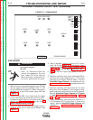
LED that
was off
7
8
9
Check AC voltage between pins specified,
it should be approximately 34VAC .
P5 pins 15 & 16 (wires 203,204)
P5 pins 7 & 8 (wires 205,206)
P5 pins 5 & 6 (wires 207,208)