


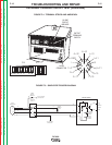


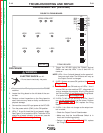

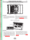


DC600 CONTROL
G3409-1
LED1
LED5
LED2
LED3
LED4
LED6
J2
J3
J1
2 (256)
(290) 7
(291) 8
1
(222)12
1 (210)
5 (231)
(255) 6
1
FIGURE F.7 CONTROL BOARD
CONTROL BOARD TEST (continued)
PROCEDURE
ELECTRIC SHOCK
can kill.
• Do not touch electrically hot parts.
1. Turn the POWER Switch ON. LEDs 1 and 3 should
turn ON.
2. If LED 1 does not come ON, but the Power Light
is ON, check for 120vac at J2 (pin 6 and pin 2).
See the Wiring Diagram.
• If the Power Light is not ON, perform the Control
Transformer Voltage Test and check the Power
Switch and associated wiring.
3. If LED 3 does not come ON but LED4 is ON, the
DC-600 has shut down due to over-current or a
fault in the control leads (75,76 & 77).
• Disconnect any control cables, welding leads or
jumpers from the terminal strips (TS1& TS2).
4. If the machine stays ON and all LEDs are correct,
the problem is external to the machine. If LED4 still
comes ON:
• Check the Output Studs and associated wiring for
a ‘shorted’ or ‘grounded’ condition.
• Check for grounds in the control circuit (Output
Control, Local/Remote Switch & TS1).
• Control Board may be defective.
NOTE: LED 4 should be OFF except in a “shutdown“
condition. If ON and machine is still function-
ing, replace the Control Board.
5. LED 5 indicates a signal to the Firing Board and
should vary in brilliance as the Output Control is
adjusted. If LED 5 is not ON or does not change:
• Make certain that LED 6 is ON. The Output
Terminal Switch the Local/Remote Switch must
be in “LOCAL” position and the Mode Switch in
CV. If switches are set properly and functional, the
Control Board may be defective.
6. LED 6 indicates a signal from the Firing Board that
the DC-600 is “triggered”. If not ON, perform the
Internal Trigger Test.
TROUBLESHOOTING AND REPAIR
F-20 F-20
DC-600
Return to Section TOC Return to Section TOC Return to Section TOC Return to Section TOC
Return to Master TOC Return to Master TOC Return to Master TOC Return to Master TOC
WARNING