


THEORY OF OPERATION
E-2 E-2
DC-600
Return to Section TOC Return to Section TOC Return to Section TOC Return to Section TOC
Return to Master TOC Return to Master TOC Return to Master TOC Return to Master TOC
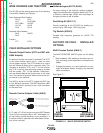
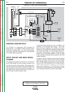
GENERAL DESCRIPTION
The DC-600 is a three-phase, SCR controlled DC
power source. It is capable of either constant current
or constant voltage output. It is rated at 600 amps,
100% duty cycle with outstanding arc characteristics
for multiple welding processes.
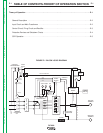
INPUT CIRCUIT AND MAIN TRANS-
FORMER
The desired three-phase input power is connected to
the DC-600 through an input contactor located in the
input box at the rear of the machine. Two phases of the
input line are also connected to the control transformer.
The secondary of the control transformer supplies 115
VAC power to the control board and to the input con-
tactor through the fault protection relay.
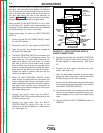
FIGURE E.2 - INPUT AND TRANSFORMER
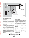
A reconnect panel allows the user to configure the
machine for the desired input voltage. This three-
phase AC input is applied to the primary of the main
transformer. The transformer changes the high voltage,
low current input power to a lower voltage, higher cur-
rent output. The finishes or “neutrals” of the main sec-
ondary coils are connected together, and the six starts
of the secondary windings are connected to the SCR
rectifier assembly.
In addition, the main transformer also has five isolated
secondary windings. There are three 32 VAC windings,
which provide power and “timing” to the firing board.
The 115 VAC winding powers the fan motor and pro-
vides the user with up to 20 amps of 115 VAC auxiliary
power at the receptacle or 14-pin MS type connector.
The 42 VAC winding provides 10 amps of power to the
14 pin MS type connector to power a wire feeder.
CONTROL
TRANSFORMER
R
E
C
O
N
N
E
C
T
CONTACTOR
FAULTPROTECTION
115VAC
MAIN
TRANSFORMER
CONTROL
BOARD
SHUNT
OUTPUT
CONTROL
MODE
SWITCH
POSITIVE
TERMINAL
NEGATIVE
TERMINAL
LATCHING
RESISTOR
F
E
E
D
B
A
C
K
F
E
E
D
B
A
C
K
SCR BRIDGE
115VAC
42VAC
T
E
R
M
I
N
A
L
S
T
R
I
P
FIRING
BOARD
CR2
CR1
CHOKE
14-pin
Amphenol
115VAC
Receptacle
Fan
Motor
32VAC
32VAC
32VAC
SIGNAL
G
A
T
E
S
I
G
N
A
L
OUTPUT
CONTROL
Secondary
Thermostat
Primary
Theromstat
1CRCoil
w
Pilot
Light
•
•
OUTPUT
TERMINAL
SWITCH
POWER
SWITCH
•
TERMINAL
STRIP 1
OUTPUT
CONTROL
SWITCH
2
115VAC
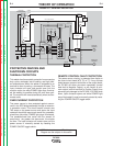
NOTE: Unshaded areas of Block Logic
Diagram are the subject of discussion