


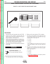
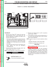
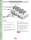
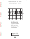

ANODE
CATHODE
REMOVE
INSULATING
PAINT
FIGURE F.14 – SCR BRIDGE ASSEMBLY
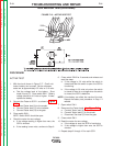
SCR BRIDGE TEST(continued)
PROCEDURE
STATIC TEST
1. Disconnect the input power from the DC-600.
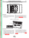
2. Remove the top and side panels and drop the
nameplate to access the PC Boards.
3. Unplug the Molex connectors from both the Control
Board and the Firing Board.
4. Scratch off some of the insulating paint from each
of the six heat sinks (anodes) and the base plate
(cathode). See Figure F.14.
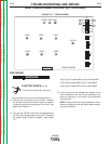
5. Using the analog ohmmeter:
• Measure the resistance from each Anode to the
Cathode plate with the Positive meter lead on the
Anodes. The resistance should be very high or
‘open’.
• Reverse the meter leads and measure all the
same points. The readings should be very high or
‘open’, and typically, will all be similar.
6. If any of the test points shows a low resistance, dis-
connect the Snubber Board from that SCR. If the
reading is still low, the SCR is defective.
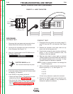
7. Continue to the Active Test.
The Active test will require constructing a test cir-
cuit or use of a commercial SCR Tester. See
Figure F.15.
TROUBLESHOOTING AND REPAIR
F-30 F-30
DC-600
Return to Section TOC Return to Section TOC Return to Section TOC Return to Section TOC
Return to Master TOC Return to Master TOC Return to Master TOC Return to Master TOC