


FIRING BOARD
G3742-[ ]
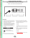
LED7
LED8
LED9
LED1
LED2
LED3
LED4
LED5
LED6
LED10
J5
J6
J7
J4
J8
(205) 8
(206) 7
(207) 6
(208) 5
4
3
2
1
16 (204)
15 (203)
14
13 (231)
12 (215)
11
10
9
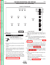
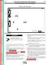
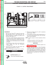
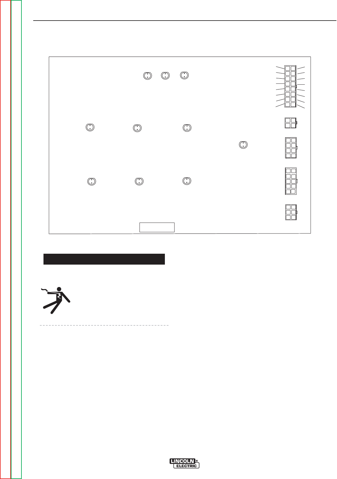
FIGURE F.11 – FIRING BOARD
MAIN TRANSFORMER VOLTAGE TEST (continued)
PROCEDURE
ELECTRIC SHOCK
can kill.
• Do not touch electrically hot parts.
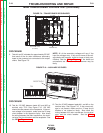
13. Remove the input power to the DC-600. Remove
the screws from the control box cover and careful-
ly lower the cover and locate plug J5 on the Firing
Board. See Figure F.11.
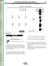
14. Turn on the DC-600 and check for approximately
32 VAC at the following pins of plug J5. These are
the phase angle winding voltages. See Figure
F.11.
Plug J5 pin-15 (lead #203) to pin-16 (lead #204)
Plug J5 pin-8 (lead #205) to pin-7 (lead #206)
Plug J5 pin-6 (lead #207) to pin-5 (lead #208)
18. If the correct primary voltages are applied to the
main transformer and any of the secondary volt-
ages are missing or not correct, the transformer
may be faulty.
NOTE: Always check the wiring between the trans-
former windings and the test points before replac-
ing the transformer.
TROUBLESHOOTING AND REPAIR
F-24 F-24
DC-600
Return to Section TOC Return to Section TOC Return to Section TOC Return to Section TOC
Return to Master TOC Return to Master TOC Return to Master TOC Return to Master TOC
WARNING