


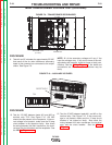
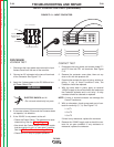
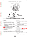


FIGURE F.15 – ACTIVE SCR TEST
SCR BRIDGE TEST(continued)
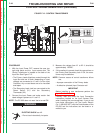
PROCEDURE
ACTIVE TEST
1. With the circuit shown in Figure F.17. One 6-volt
lantern battery can be used. Set the voltmeter
scale low, at approximately 0-5 volts or 0-10 volts.
a. Test the voltage level of the battery. Short
leads (A) and (C). Close switch SW-1. Battery
voltage should be 4.5 volts or higher. If lower,
replace the battery.
2. Connect the Tester to SCR 1 as shown in Figure
F.17.
a. Connect Tester lead (A) to the anode.
b. Connect Tester lead (C) to the cathode.
c. Connect Tester lead (G) to the gate.
3. Close switch SW-1.
NOTE: Switch SW-2 should be open.
4. Check the meter for zero voltage.
a. If the voltage reading is higher than zero, the
SCR is shorted.
b. If the reading is zero volts, continue to Step 6.
6. Close switch SW-2 for 2 seconds and release and
read the meter.
a. If the voltage is 3-6 volts while the switch is
closed and after the switch is open, the SCR is
functioning.
b. If the voltage is 3-6 volts only when the switch
is closed or there is no voltage when the switch
is closed, the SCR is defective.
NOTE: A low battery can affect the results of the test.
Repeat the battery test procedure in Step 1 if
needed.
7. Open switch SW-1.
8. Reconnect the Tester leads. See Figure F.17.
a. Connect Tester lead (A) to the cathode.
b. Connect Tester lead (C) to the anode.
c. Disconnect Test lead (G) from the gate.
9. Close switch SW-1.
10. Read the meter for zero voltage.
a. If the voltage is zero, the SCR is functioning.
b. If the voltage is higher than zero, the SCR is
shorted.
11. Repeat steps 2 through 10 for each SCR.
TROUBLESHOOTING AND REPAIR
F-31 F-31
DC-600
Return to Section TOC Return to Section TOC Return to Section TOC Return to Section TOC
Return to Master TOC Return to Master TOC Return to Master TOC Return to Master TOC