


A
A
A
A
A
A
A
A
A
A
A
A
A
A
A
A
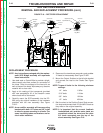
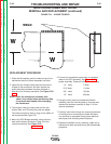
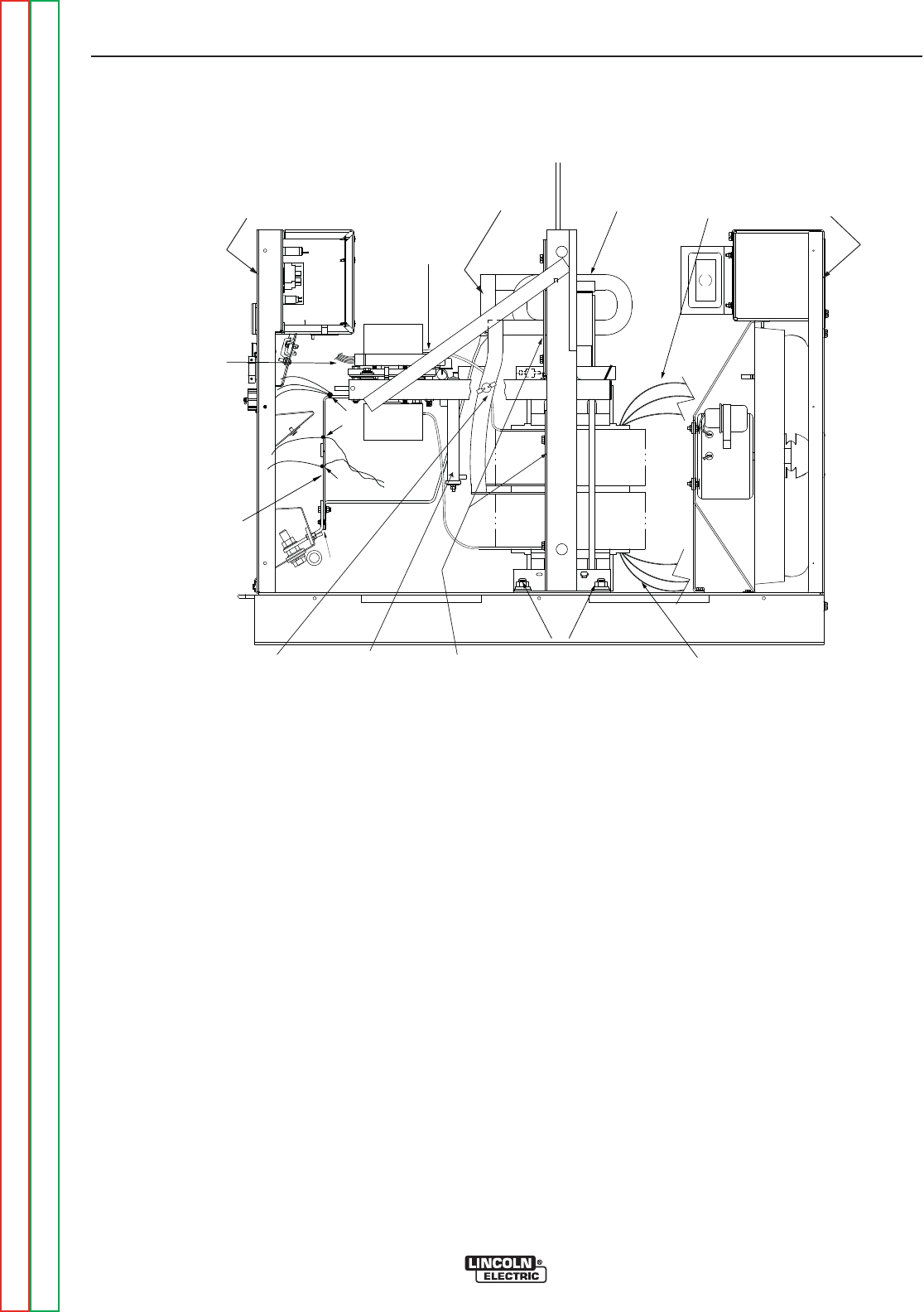
OUTPUT
SHUNT
210
215
SECONDARY
LEAD (6 PLACES)
CONNECTION
STRAP
OUTPUT
CHOKE
MOUNTING
HARDWARE
(4 PLACES)
FIRING BOARD
CONNECTORS
(J-4 & J-5)
AUXILIARY
LEADS
PRIMARY
LEADS
NEGATIVE
OUTPUT LEAD
SECONDARY
THERMOSTAT
INPUT
ACCESS
COVER
CONTROL
PANEL
BAFFLES
30 Ω
RESISTOR
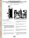
FIGURE F.19 – TRANSFORMER REMOVAL
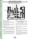
MAIN TRANSFORMER AND CHOKE
REMOVAL AND REPLACEMENT (continued)
REMOVAL PROCEDURE
1. Disconnect all input power and remove the case top,
sides, terminal strip cover and the input access cover
and drop the Control Panel.
2. Remove the fiber baffles that are around the Choke
and Transformer and save for installation when the
new transformer is installed.
3. Disconnect the Transformer Primary leads from the
reconnect panel.
NOTE: Pay close attention to the positioning of the
brass and steel hex nuts for reassembly.
4. Pull the leads out of the Input Box. This will require
removing some of the RTV sealant from the inside of
the box.
NOTE: Tag any leads where the Lincoln lead num-
bers are not evident to facilitate reassembly.
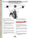
5. Cut off the crimp connectors from the fan leads
(#31 A) and lead #41 and #42A. Tag any leads
where the Lincoln lead number is not evident.
NOTE: Cut ties and remove sleeving as necessary
to perform the following steps. Note the
positioning for reassembly.
6. Disconnect leads #271 and #272 from th e Contactor
coil and pull them through the back of the Input Box.
7. Disconnect the leads from the Secondary
Thermostat and separate the X2 lead from te #256
lead.
8. Pull the three leads from Step 4 and the #271 lead-
towards the Control Box.
9. Disconnect the #41, #2, and #4 leads from the
Terminal Strip and separate the “piggy-back” con-
nections.
10. Separate the three in-line connectors between J5
of the Firing Board and J2 of the Control Board
(Leads 231, 290, & 291).
11. Unplug J5 and J4 from the Firing Board and work
them through the bottom of the Control Box. It will
be necessary to remove the grommet with the J4
connector. (A new grommet is provided with the
replacement transformer).
TROUBLESHOOTING AND REPAIR
F-46 F-46
DC-600
Return to Section TOC Return to Section TOC Return to Section TOC Return to Section TOC
Retur n to Master TOC Return to Master TOC Return to Master TOC Return to Master TOC