


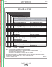

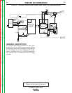

THEORY OF OPERATION
E-6 E-6
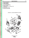
CLASSIC® 300D & 300G
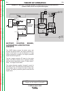
ENGINE, GENERATOR ARMATURE
AND FRAME, ALTERNATOR STA-
TOR AND ROTOR
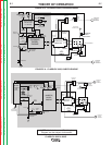
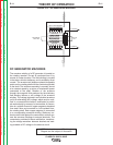
EXCITATION (FLASHING)
When the engine is started and running, voltage
produced by residual magnetism in the DC weld-
ing generator passes through a “flashing” diode,
and is applied to the alternator rotor via a brush
and slip ring configuration. This excitation (“flash-
ing”) voltage magnetizes the rotor lamination. The
alternator rotor is connected to the armature shaft,
which is mechanically coupled to the engine. The
rotating magnet (rotor) induces a voltage in the
stationary windings of the alternator stator.
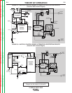
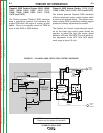
AUXILIARY AND FIELD FEEDBACK
COILS
There are two isolated windings incorporated in
the stator lamination assembly. One of these
windings is tapped and provides 115VAC and
230VAC of auxiliary power to the appropriate
receptacles. The other 115VAC isolated winding is
rectified to a DC voltage and is used to supply
field feedback voltage to the rotor. It also supplies
voltage, through the generator field rheostat con-
trol, to the field shunt windings in the main gener-
ator frame.
INTERPOLE AND SERIES COILS
The generator armature rotates within the mag-
netic field created by the shunt field windings. A
DC voltage is induced in the armature and is
transferred, through the armature commutator
and brushes, to the series and interpole coils. The
interpole coils, which are connected in series with
the positive output terminal, are located so as to
counteract any magnetic influences that could
cause mechanical distortion in the rotating arma-
ture. The series coils are designed to oppose or
“buck” the DC voltage that is generated in the
armature.
CURRENT RANGE SELECTOR
The selector switch acts as a coarse current
adjustment by allowing for varying amounts of
series windings to be included in the welding cur-
rent path. The series coils and selector switch are
connected in series with the negative output ter-
minal.
FINE CURRENT ADJUSTMENT
The field rheostat control functions as a fine out-
put current adjustment by controlling the current
through the shunt windings. This controls the
amount of magnetism created in the shunt field
windings. Open circuit weld voltage can also be
controlled by the field rheostat control.
ENGINE HIGH IDLE RPM (OCV)
ADJUSTMENT
Classic® 300G (Codes 10659, 10912, and 11135)
The Classic® 300G utilizes an electronic engine
control system manufactured by Zenith fuel sys-
tems LLC. This system maintains a steady RPM
by constantly sensing engine speed and making
adjustments as needed.
A potentiometer mounted on the output rail allows
the operator to adjust the high idle engine speed
between 1700 and 1800 RPMʼs in 20 RPM incre-
ments. This is to allow further adjustment of the
welding generator open circuit voltage (OCV).
Total OCV adjustment range is about 10 Volts.
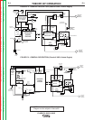
NOTE: Unshaded areas of Block Logic
Diagram are the subject of discussion
Return to Section TOC Return to Section TOC Return to Section TOC Return to Section TOC
Return to Master TOC Return to Master TOC Return to Master TOC Return to Master TOC