


ALTERNATOR STATOR REMOVAL AND REPLACEMENT (continued)
TROUBLESHOOTING AND REPAIR
F-70 F-70
CLASSIC® 300D & 300G
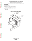
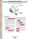
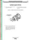
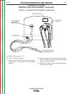
FIGURE F.7 – COMMUTATOR WRAP-AROUND REMOVAL
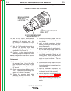
PROCEDURE
1. Turn the engine OFF.
2. Perform the Alternator Rotor Removal
procedure.
3. With the 1/2" wrench, remove the four nuts
and bolts holding the case top and doors
assembly to the welder frame. Carefully lift
up and remove the top and doors assembly.
4. With the 3/8" nut driver, remove the two
leads from the alternator brush holder
assembly. Note lead placement. Set brush
holder aside.
5. With the slot head screwdriver, remove the
commutator wraparound. See Figure F.7.
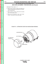
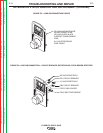
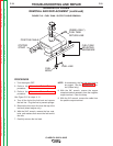
6. Disconnect the yellow and white wires at the
in-line connectors. See the Wiring Diagram
and Figure F.8.
7. Disconnect the two yellow leads. One is
located at the field bridge and the other at
the field fuse holder. Cut any necessary
cable ties. See Figure F.8 and F.9.
8. Remove the tape and using the 3/8"
wrench and slot head screw driver, discon-
nect the black auxiliary power lead from
the current transformer. Cut any neces-
sary cable ties. See the Wiring Diagram
and Figure F.8.
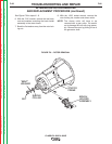
9. Remove the red auxiliary power lead from
the CB4 circuit breaker. See the Wiring
Diagram and Figure F.9.
10. Remove the white auxiliary power lead
from the 115VAC receptacle. Cut any nec-
essary cable ties. See Figure F.9.
NOTE: The CB1 circuit breaker may have to
be removed to access the terminal for
the white lead.
11. Remove the red lead from the negative ter-
minal of the field rectifier bridge. See
Figure F.9.
12. Remove the black lead from the positive
terminal of the field rectifier bridge. See
Figure F.9.
C
OMMUTATOR
W
RAPAROUND
ALTERNATOR
BRUSH HOLDER
ASSEMBLY
(REMOVED)
Return to Section TOC Return to Section TOC Return to Section TOC Return to Section TOC
Return to Master TOC Return to Master TOC Return to Master TOC Return to Master TOC