


Check that the brush holders are properly installed
and positioned correctly. See the Welding
Generator Brush and Commutator Inspection
and Service procedure.
Start the engine, place the idle switch in the high
idle position, and seat the brushes using a com-
mutator stone. See the Welding Generator Brush
and Commutator Inspection and Service
Procedure.
Place the range selector switch in the maximum
position. Use a load bank to apply a 100% duty
cycle load (250 amps @ 30 volts). Look at the
brushes while the load is applied. If excessive
sparking is observed, adjust the rocker position to
minimize sparking. Generally, moving the rocker
slightly in the direction of the armature rotation will
reduce sparking.
Continue running the machine under load for at
least 30 minutes to bring the machine up to normal
operating temperature and to fully seat the brush-
es.
Check for Max output.
Remove the load, set the fine current control and
rheostat to maximum, and then adjust the load
bank to apply a 300 Amp load to the machine.
Measure the output voltage, it should read:
• From 33 to 42 VDC for Classic® 3000 and
Classic® 300D Perkins models.
• From 34 to 48 VDC for Classic® 300D Kubota
models.
Measure the engine RPM, it should measure:
• From 1780 to 1810 RPM, for Classic® 3000 mod-
els
• From 1650 to 1750 RPM, for Classic® 300D
Perkins models
• From 1790 to 1810 RPM, for Classic® 300D
Kubota models
If the engine RPM is not within specification,
Perform the Engine RPM Adjustment Test, if the
engine high idle RPM is normal, but the load RPM
is significantly less than specified above, the
engine or governor may be malfunctioning. See the
engine troubleshooting procedures in this manual
and/or have the engine serviced or repaired by a
qualified engine technician.
If the weld output voltage is lower than specified
above, the rocker position will need to be adjusted.
Generally, moving the rocker opposite the arma-
ture rotation direction will increase output voltage.
When making this adjustment, the rocker should
only be moved in very small increments. The
adjustment may need to be repeated several times
to achieve the desired result.
Check the OCV, (Open Circuit Voltage)
Remove the load and check the voltage at the out-
put studs. The voltage should measure from 93 to
99 Volts DC.
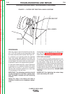
After the rocker has been adjusted and the
machine is operating normally, the rocker locking
screw should be tightened to 70-75 Inch-Lbs.
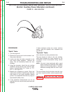
If new parts had been installed, the new rocker
and/or exciter bracket location should be marked
with a 1/8" drill mark. See Figure F.1.
TROUBLESHOOTING AND REPAIR
F-39 F-39
CLASSIC® 300D & 300G
ROCKER ADJUSTMENT PROCEDURE (continued)
Return to Section TOC Return to Section TOC Return to Section TOC Return to Section TOC
Return to Master TOC Return to Master TOC Return to Master TOC Return to Master TOC