


SHUNT FIELD CIRCUIT VOLTAGE TEST PROCEDURE (continued)
PROCEDURE
1. Turn the engine off.
2. Open either or both of the side doors.
NOTE: Secure the doors in the open position
using the door restraint system. If the
machine does not have a door restraint
system, remove the doors or securely
restrain them to prevent them from falling
closed.
3. Place the field rheostat in the maximum posi-
tion.
4. Place the remote/local switch in the local posi-
tion.
5. Place the idle switch in the high idle position,
start the engine and allow it to stabilize at high
idle RPM.
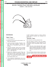
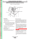
6. Locate the J5 Molex connector located in the
harness close to the generator lead block.
7. Test for DC voltage between the brown and
blue wires, pins #3 and #5. The voltage should
be between 123 and 133 VDC.
8. If the measured voltage is normal, but there is
still no usable output from the welding genera-
tor, perform the Shunt Field Coil Resistance
and Ground Test.
9. If the correct voltage is not present at the J5
harness plug, check for voltage at the positive
and negative terminals of the field bridge rectifi-
er. See Wiring Diagram.
10. If 123 to 133 VDC is present at the field bridge
rectifier, check the wiring and connections
between the rectifier, the rheostat, the
remote/local switch, and the J5 Molex connec-
tor. Check the rheostat and the remote/local
switch for proper operation. See Wiring
Diagram.
TROUBLESHOOTING AND REPAIR
F-48 F-48
CLASSIC® 300D & 300G
Return to Section TOC Return to Section TOC Return to Section TOC Return to Section TOC
Return to Master TOC Return to Master TOC Return to Master TOC Return to Master TOC