


PROCEDURE
1. Turn the engine OFF.
2. Perform the Alternator Rotor Removal pro-
cedure.
3. Perform the Alternator Stator Removal pro-
cedure.
4. Perform the Generator Frame Removal pro-
cedure.
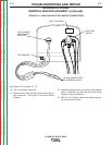
5. Using the rope sling, support the armature.
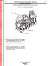
6. Make sure the engine is supported with the
wood or steel blocks.
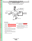
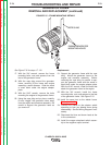
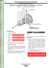
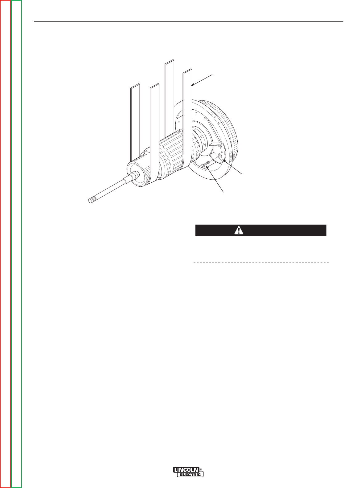
7. With the 5/8" wrench, remove the eight bolts
and lock washers holding the blower paddles
and the armature to the engine flywheel. See
Figure F.16.
8. With the armature supported and “balanced”
in the rope sling, carefully rotate the armature
1/8 turn in either direction to release.
The armature is now free to be removed from the
engine.
Replacement:
9. Support the armature with the rope sling.
Mount the armature to the engine, rotating it
1/8 of a turn in either direction to achieve
proper attachment. Before removing the
rope sling, be careful to support the arma-
ture with the wood or steel blocks under the
engine. With the 5/8" wrench, install the
eight bolts and lock washers that attach the
blower paddles and the armature to the
engine flywheel.
10.
Perform the replacement procedures accord -
ing
to each of the following:
Generator Frame Removal and Replacement
Alternator Stator Removal and Replacement
Alternator Rotor Removal and Replacement
TROUBLESHOOTING AND REPAIR
F-82 F-82
CLASSIC® 300D & 300G
GENERATOR ARMATURE
REMOVAL AND REPLACEMENT PROCEDURE (continued)
FIGURE F.16 – BLOWER PADDLE REMOVAL
BLOWER
PADDLE/ARMATURE
MOUNTING BOLTS (8)
BLOWER PADDLE
ROPE SLING
CAUTION
Return to Section TOC Return to Section TOC Return to Section TOC Return to Section TOC
Return to Master TOC Return to Master TOC Return to Master TOC Return to Master TOC