


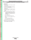
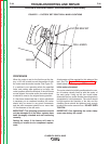
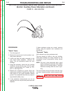


FIGURE F.2 – LEAD LOCATION
EXCITER ROTOR RESISTANCE AND GROUND TESTS PROCEDURE
(Exciter / Auxiliary Power Alternator) (continued)
PROCEDURE
"Static" Tests:
1. Turn the engine off.
2. Remove the round cover from the exciter / aux-
iliary power alternator.
3. Locate and label the leads connected to the
rotor brush holder assembly. Remove the
leads. This will electrically isolate the rotor
windings.
4. Using the ohmmeter, check the rotor winding
resistance across the slip rings. Normal resis-
tance is approximately 41.5* ohms, at 77°F.
(25° C.) See Figure F.2
5. Measure the resistance to ground. Place one
meter probe on either of the slip rings. Place the
other probe on any good unpainted chassis
ground. The resistance should be very high, at
least 500,000 (500k) ohms.
6. If the resistance measurements are not as
specified the rotor may be faulty and should be
replaced.
If these resistance values are normal, continue
testing, using the dynamic rotor resistance and
ground test.
"Dynamic" Tests:
(Also referred to as flying resistance test)
This test checks for faults in the rotor winding,
while these windings are being stressed by the
mechanical forces encountered during normal
operation.
NOTE: This test is best performed with a good
quality analog type ohmmeter. Many digital
meters will not provide stable or accurate
resistance readings while the rotor is spin-
ning.
This test requires that the brushes and slip rings
are clean, in good condition, and are properly seat-
ed.
Perform the Brush and Slip RIng Service
Procedure if necessary.
TROUBLESHOOTING AND REPAIR
F-42 F-42
CLASSIC® 300D & 300G
Return to Section TOC Return to Section TOC Return to Section TOC Return to Section TOC
Return to Master TOC Return to Master TOC Return to Master TOC Return to Master TOC