


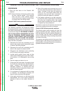

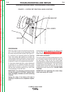

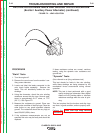

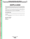

ROCKER
DRILL MARKS
EXCITER BRACKET
FIGURE F.1 – FACTORY SET POINT DRILL MARK LOCATIONS
ROCKER ADJUSTMENT PROCEDURE (continued)
PROCEDURE
When the rocker is set for the first time at the fac-
tory, a 1/8" drill is used to mark the position of both
the rocker and the exciter bracket. See Figure F.1
If a machine is not operating within the specified
limits, and nothing else appears to be faulty, the
rocker position should be checked. If the drill marks
are not aligned, the rocker and/or the exciter brack-
et should be reset to the original factory position.
If it has been determined that a rocker adjustment
is necessary on an unaltered machine; the rocker
should only be moved in very small increments,
and the total movement should be no more than
1/2 the diameter of the drill mark.
IMPORTANT! The following procedures should
only be attempted if all the other systems have
been thoroughly checked and are functioning
normally.
Setting the rocker if the factory drill mark is
missing or invalid due to component replace-
ment:
A tachometer will be required for this phase of the
test. See The Engine RPM Adjustment Test for
details about measuring engine RPM.
Initial rocker placement:
The rocker should be initially positioned so the cen-
ter of brushes visually lines up with the center of
the main poles. Lining up the four brush holder
studs with the four exciter bracket mounting bolts is
acceptable for initial placement. The rocker should
be tight against the shoulder of the hub and the
clamping screw should be tightened only enough
to assure the rocker cannot move. DO NOT OVER
TIGHTEN.
IMPORTANT: Over tightening the rocker clamp
screw can destroy the rocker.
TROUBLESHOOTING AND REPAIR
F-38 F-38
CLASSIC® 300D & 300G
Return to Section TOC Return to Section TOC Return to Section TOC Return to Section TOC
Return to Master TOC Return to Master TOC Return to Master TOC Return to Master TOC