


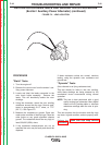

EXCITER STATOR SHORT CIRCUIT & GROUND TEST PROCEDURE
(continued)
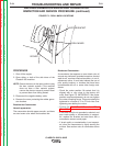
PROCEDURE
1. Open either, or both of the side doors.
Note: Secure the doors in the open position using
the door restraint system. If the machine
does not have a door restraint system,
remove the doors or securely restrain them
to prevent them from falling closed.
2. Make sure that nothing is plugged into the aux-
iliary receptacles.
3. Disconnect and isolate the ground lead con-
nected to the neutral side of the 115 VAC auxil-
iary receptacle. See the wiring diagram.
4. Disconnect and isolate the exciter winding
leads. (Leads 214 and 215) In earlier codes,
these wires were color coded yellow and did not
have numbers. See the wiring diagram.
5. Using an ohmmeter; check the resistance
between the following points. Resistance
should read very high, 500,000 (500k) ohms
minimum.
• From chassis ground and one of the exciter
winding leads.
• From chassis ground and one of the neutral
terminals of the 115 VAC receptacle. (The neu-
tral terminal is the longer of the two slots.)
•From one of the neutral terminals of the 115
VAC receptacle to one of the exciter leads.
6. If any of these readings are less than 500,000
(500k) ohms, be certain that the windings are
completely dry and check for grounded compo-
nents or wiring that remain connected to the
stator, such as circuit breakers, receptacles,
etc. See wiring diagram. If necessary, discon-
nect and isolate the stator leads as close to the
stator winding as possible.
7. If the low resistance to ground, or between indi-
vidual stator windings is determined to be with-
in the stator, the stator is defective and should
be replaced.
TROUBLESHOOTING AND REPAIR
F-50 F-50
CLASSIC® 300D & 300G
Return to Section TOC Return to Section TOC Return to Section TOC Return to Section TOC
Return to Master TOC Return to Master TOC Return to Master TOC Return to Master TOC