


EXCITER ROTOR RESISTANCE AND GROUND TESTS PROCEDURE
(Exciter / Auxiliary Power Alternator) (continued)
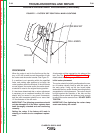
7. Insulate the lead wires that had been discon-
nected from the brushes during the static rotor
resistance test. Position and secure them so
they cannot become damaged by the spinning
rotor. It is recommended that the ohmmeter
leads be securely attached to the brush termi-
nals, using clips or terminals BEFORE starting
the engine.
8. Start the engine and run it at high idle speed
(1800 RPM). The resistance should read
approximately 42* ohms at 77
0
F (25
0
C).
9. Shut off engine, and move one of the ohmmeter
leads to a good clean chassis ground connec-
tion.
10. Restart the engine and run it at high idle speed
(1800 RPM). The resistance should be very
high, at least 500,000 (500k) ohms.
11. If the resistance readings differ significantly
from the values indicated, recheck the brushes
and the brush spring tension. If the brushes
and slip rings are good, replace the rotor.
12. Securely connect the leads to the brush termi-
nals (see wiring Diagram) and replace the
alternator cover if testing and service is com-
plete.
*NOTE: The resistance of the copper windings will
change with temperature. Higher temperatures will
produce higher resistance, and lower temperatures
will produce lower resistance.
TROUBLESHOOTING AND REPAIR
F-43 F-43
CLASSIC® 300D & 300G
Return to Section TOC Return to Section TOC Return to Section TOC Return to Section TOC
Return to Master TOC Return to Master TOC Return to Master TOC Return to Master TOC