


THEORY OF OPERATION
E-10 E-10
CLASSIC® 300D & 300G
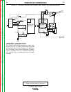
When the idle switch is in the auto position, and
welding current is being drawn, the reed switch
CR2 is closed. This signals the idler PC board to
deactivate the idle solenoid, allowing the governor
to increase the engine speed to high RPM. When
auxiliary power is being used, the current is
passed through the toroidal current transformer.
This also signals the idler PC board to deactivate
the idle solenoid. When welding ceases or the
auxiliary load is removed, a preset time delay of
about 15 seconds begins. When this 15 second
delay has passed, the PC board activates the idle
solenoid, as described above, and pulls the
engine governor linkage to the low idle RPM posi-
tion. If welding is resumed, or an auxiliary load is
applied during this delay, the engine RPM will
remain high.
When the idle switch is in the high position, the
reed switch CR2 is bypassed, signaling the PC
board to leave the solenoid inactive
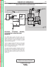
Classic® 300D Kubota (Codes: 11112, 11113,
11243, 11244, 11413, 11414, 11474, and 11475)
The Kubota engine control unit (ECU) used in the
Classic® 300D controls whether the engine oper-
ates at high idle or low idle. Grounding pin #31 of
the ECU signals that high RPM is required and
the engine immediately accelerates to high idle
RPM. Opening the circuit between pin #31and
chassis ground will cause the engine RPM to drop
to low idle speed, after a delay of about 15 sec-
onds. If the chassis ground to pin #31 circuit re-
closed during this delay, engine RPM will remain
high.
The current sensor PC board detects current flow
in both the auxiliary and the weld circuits. When
sufficient current is flowing in either of these cir-
cuits, the lead connected to pin #31 is grounded,
signaling that high RPM is required. When cur-
rent flow ceases, the lead connected to pin #31 is
disconnected from chassis ground, and the
engine idles down after the delay described
above.
The idle switch and the current sensing PC board
are wired in parallel between chassis ground and
the pin#31 circuit described above. When the idle
switch is set to the high position, the contacts are
closed and the ECU operates the engine continu-
ously at high RPM. When the idle switch is in the
Auto position, the contacts are open, and the cur-
rent sensor PC board controls whether the pin
#31 circuit is grounded or open.
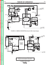
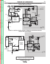
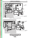
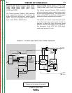
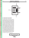
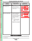
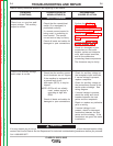
NOTE: Unshaded areas of Block Logic
Diagram are the subject of discussion
Return to Section TOC Return to Section TOC Return to Section TOC Return to Section TOC
Return to Master TOC Return to Master TOC Return to Master TOC Return to Master TOC