


THEORY OF OPERATION
E-9 E-9
CLASSIC® 300D & 300G
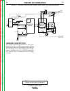
ENGINE IDLER CIRCUIT
Classic® 300G (Codes 10659, 10912, and
11135)
The Zenith ECU used in the Classic® 300G con-
trols whether the engine operates at high idle or
low idle. Closing the circuit between pins #11 and
#13 of the ECU signal that high RPM is required
and the engine immediately accelerates to high
idle RPM. Opening this will cause the engine
RPM to drop to low idle speed, (about 1360 RPM)
after a delay of about 15 seconds. If the pin #11
to pin #13 circuit is re-closed during this delay,
engine RPM will remain high.
The current sensor PC board detects current flow
in both the auxiliary and the weld circuits. When
sufficient current is flowing in either of these cir-
cuits, the current sensor PC board closes the #11
- #13 circuit, when current flow ceases, the circuit
is opened.
The idle switch and the current sensing PC board
are wired in parallel across the #11 - #13 circuit
described above. When the idle switch is set to
the high position, the contacts are closed and the
ECU operates the engine continuously at high
RPM. When the idle switch is in the Auto position,
the contacts are open, and the current sensor PC
board has control of the #11 - #13 circuit.
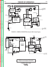
Classic® 300D Perkins (Codes 10545, 10546,
10657, 10658, 10911, and 10927)
The above models use a high speed solenoid,
connected to the governor linkage, and operated
by the idler/engine protection PC board. In these
machines, the solenoid increases the RPM when
activated.
When the idle switch is in the auto position, and
welding current is being drawn, the reed switch
CR2 is closed. This signals the idler PC board to
activate the high speed solenoid, which then
increases the engine speed to high idle RPM.
When auxiliary power is being used, the current is
passed through the toroidal current transformer.
This also signals the idler PC board to activate the
high speed solenoid. When welding ceases or
the auxiliary load is removed, a preset time delay
of about 15 seconds starts. When this 15 second
delay has passed, the idler PC board deactivates
the high speed solenoid, and allows the machine
will return to a low speed condition. If welding is
resumed, or an auxiliary load is applied during this
delay, the solenoid will remain active and the
engine RPM remains high.
When the idle switch is in the high position, the
reed switch CR2 is bypassed, signaling the PC
board to activate the solenoid.
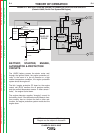
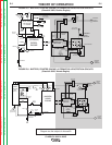
Classic® 300D Perkins (Codes 11110, 11111,
11248, 11249, 11280, 11281, 11411, 11412,
11472, and 11473)
The above models use a two winding idle sole-
noid, connected to the governor linkage, and
operated by the idler/engine protection PC board.
The engine normally runs at high RPM, and is
controlled by the governor. When the idle switch
is in the auto position and no weld or auxiliary
loads are applied, the idler/engine protection PC
board starts a 15 second delay. When this delay
has passed, both the pull and hold coils of the
solenoid are activated. After about 0.75 seconds,
the pull coil is deactivated leaving the still active
hold coil to maintain the low idle position of the
solenoid.
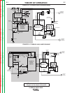
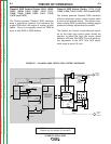
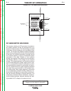
NOTE: Unshaded areas of Block Logic
Diagram are the subject of discussion
Return to Section TOC Return to Section TOC Return to Section TOC Return to Section TOC
Return to Master TOC Return to Master TOC Return to Master TOC Return to Master TOC