


WELDING GENERATOR BRUSH AND COMMUTATOR
INSPECTION AND SERVICE PROCEDURE (continued)
PROCEDURE
1. Shut off the engine.
2. Open either, or both of the side doors of the
Classic® 300 machine.
NOTE: Secure the doors in the open position using
the door restraint system. If the machine
does not have a door restraint system,
remove the doors or securely restrain them
to prevent them from falling closed.
3. Disconnect the negative battery cable.
4. Remove the cover protecting the welder gener-
ator brushes.
Examine the Commutator:
Normal appearance:
The commutator should appear smooth, and have
an even brown color where the brushes ride.
Blackened Commutator:
A commutator that appears an even black color all
around may indicate a grounded armature, shorted
weld circuit, a serious overload condition, or out-of-
adjustment rocker. It could also indicate the use of
poor quality brushes, or brushes that have been
contaminated with oil or some other foreign sub-
stance.
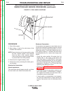
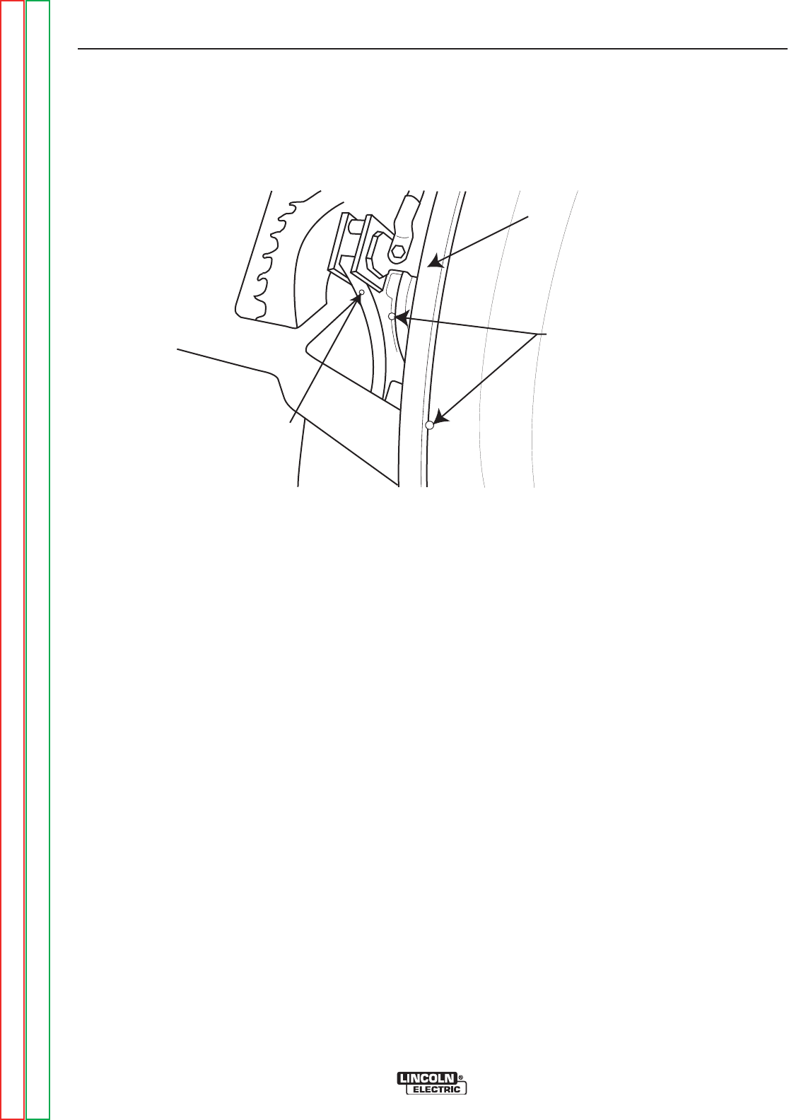
• Check the rocker position. Be certain that it is
aligned with or very close to the factory drill
mark. See Figure F.3. IMPORTANT: If the rocker
position requires adjustment, do not over tighten
the rocker clamping screw. This screw should be
tightened to a torque of 70 to 75 Inch-Lbs. Over
tightening can destroy the rocker.
• Perform the Weld Circuit Ground and Short
Circuit Test.
• If the weld circuit is not grounded or shorted, and
poor brush quality or contamination is suspect-
ed, replace the brushes and seat them with a
commutator stone or sand paper.
• If brush quality or contamination is not suspect-
ed, clean the commutator by lightly stoning the
surface. See caution note on commutator stone
use.
TROUBLESHOOTING AND REPAIR
F-54 F-54
CLASSIC® 300D & 300G
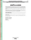
FIGURE F.3 - DRILL MARK LOCATIONS
ROCKER
DRILL MARKS
EXCITER BRACKET
Return to Section TOC Return to Section TOC Return to Section TOC Return to Section TOC
Return to Master TOC Return to Master TOC Return to Master TOC Return to Master TOC