


SHUNT FIELD COIL RESISTANCE AND GROUND TEST
PROCEDURE (continued)
PROCEDURE
1. Turn the engine off.
2. Open either or both of the doors on the
machine.
NOTE: Secure the doors in the open position using
the door restraint system. If the machine does not
have a door restraint system, remove the doors or
securely restrain them to prevent them from falling
closed.
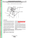
Test the shunt coil resistance:
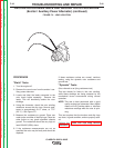
3. Remove the jumper plug or wire feed module
harness plug from J5. Locate the brown and
blue wires in J5, (pin numbers 3 and 5). Check
the resistance between these two leads.
Resistance should measure about 59 ohms at
77°F. (25° C.)
NOTE: It is always best to place probes in the lead
end of Molex connectors. Molex pins can
be easily damaged if probes are inserted in
the connection pin end.
4. If the resistance reading is correct, proceed to
the Shunt Field Coil Resistance and Ground
Test
5. If the resistance is significantly higher than 59*
ohms, check the wiring between the test points
and the shunt coils. Check the lead wire con-
necting the two shunt coils together inside the
generator frame. See the wiring diagram and
the internal generator diagram. If these lead
wires and connections are undamaged, one of
the coils is likely open. Replace the shunt field
coil set.
6. If the resistance is significantly lower than 59*
Ohms, check the wiring between the test points
and the coils for damaged insulation, pinched
wires, etc. If the lead wires and insulation are in
good condition, replace the shunt coil set.
Shunt coil ground test:
7. With the jumper plug or wire feed module
unplugged from J5, measure the resistance
between either the brown or blue wires and a
good clean chassis ground. The resistance
should be very high, 500,000 (500k) Ohms min-
imum.
8. If the resistance is still lower than 500,000
(500k) Ohms, check the shunt coil lead wires
between the test points and the coils. Also
check the lead wire connecting the two shunt
coils together inside of the generator. Look for
pinched wires and damaged insulation. If the
low resistance is determined to be between
chassis wound and one of the shunt coils,
replace the coil set.
9. Reconnect the wires and replace any covers
that have been removed.
*NOTE: The resistance in the copper windings will
change with temperature. Higher temperatures will
produce slightly higher resistance, and lower tem-
peratures will produce slightly lower resistance.
TROUBLESHOOTING AND REPAIR
F-46 F-46
CLASSIC® 300D & 300G
Return to Section TOC Return to Section TOC Return to Section TOC Return to Section TOC
Return to Master TOC Return to Master TOC Return to Master TOC Return to Master TOC