


FLASHING VOLTAGE TEST PROCEDURE (continued)
PROCEDURE
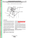
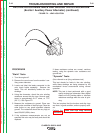
1. Remove the cover from the exciter / auxiliary
power alternator.
2. Connect the volt meter probes to the brush ter-
minals. See the wiring diagram.
3. Remove one of the AC input leads from the field
bridge rectifier.
4. Set the idle switch to "HIGH" and the
RUN/STOP switch to "RUN", and start the
engine.
NOTE: The meter should read about 4 to 6 VDC. If
this voltage reading is correct, the test is
complete. If the voltage measures zero or
significantly lower than specified check for
the following:
• An open flashing diode.
• A poor connection in the flashing circuit.
• Polarity of the main generator may be
reversed.
• The rotor winding maybe shorted,
• The field bridge rectifier may be shorted.
5. Reconnect the AC lead to the Field Bridge.
6. With the engine running at High speed, the nor-
mal rotor voltage is 123 to 133VDC.
TROUBLESHOOTING AND REPAIR
F-36 F-36
CLASSIC® 300D & 300G
Return to Section TOC Return to Section TOC Return to Section TOC Return to Section TOC
Return to Master TOC Return to Master TOC Return to Master TOC Return to Master TOC