


Front Panel
AWG5000 Series Quick Start User Manual
11
Front Panel
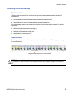
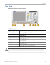
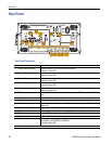
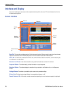
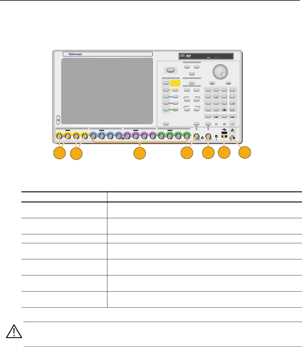
The following figure shows the front panel of the AWG5014:
Front Panel Connectors
Connector Description
1. Ch 1 Analog Output These connectors supply analog signals.
Connector type: BNC
2. Ch 1 Marker Output These connectors supply marker 1 and marker 2 signals.
Connector type: BNC
3. Ch 2 to Ch 4 connectors Analog and marker output connectors for Ch 2 to Ch 4.
4. Trigger Input External trigger signal is applied to this connector.
Connector type: BNC
5. Event Input Event signal is applied to this connector.
Connector type: BNC
6. USB Two USB connectors are present on the front panel.
Connect a USB device.
7. DC Output This connector supplies four lines of DC voltage.
Connector type: 2.54 mm 2 x 4 pin header (female)
AWG
5014
1.2 GS/s
Arbitrary Waveform Generator
Analog Analog Mkr 1 Mkr 2 Analog Analog Mkr 1 Mkr 2 Analog Analog Mkr 1 Mkr 2 Analog Analog Mkr 1 Mkr 2
Channel 1 Channel 4Channel 3Channel 2
DO NOT APPLY EXTERNAL SIGNAL
!
Amplitude
Marker 1
Marker 2
Offset
DC
Output
-3 V to +5 V
100 mA
Panel
Lock
HDD
Sampling Rate
Timing
File
Level
All Outputs
ABC
E
D
F
Channel
High
High
Low
Low
Bksp
DeleteCancel
Enter
Open
Save
Factory Default
Touch
Screen
On/Off
897
T/p
4 6
G/n
123
M/
Ch
Ch
3
Ch
Ch
3
Ch
3
0
/
On
On
On
On
On
On
On
On
On
On
On
On
On
On
On
On
On
On
Event
Input
Trigger
Input
Force
Event
Force
Trigger
14
CAUTION
TURN OFF OUTPUTS
BEFORE CHANGING
CABLES OR
POWERING DUT.
!
5V
RMS
!
O
f
f
O
f
f
On
On
On
On
On
On
Ch
Ch
2
Ch
Ch
2
Ch
2
Ch
Ch
1
Ch
Ch
1
Ch
1
Run
Run
Run
Run
Run
Run
GND
7
2
3
6
5
4
1
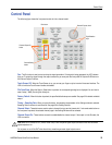
CAUTION. Always turn off the signal outputs when you connect or disconnect cables to/from the signal outputs connectors.
If you connect a DUT while the instrument signal outputs are in the On state, it may cause damage to the instrument or
DUT.