


Interface and Display
AWG5000 Series Quick Start User Manual
27
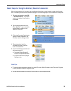
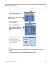
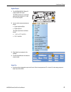
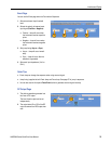
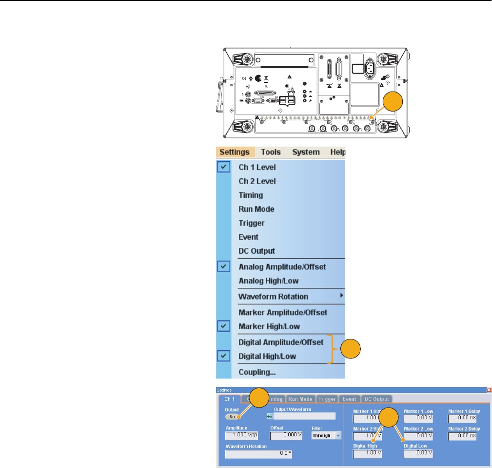
Digital Output
Quick Tip
■ Each channel has independent output on/off control. When the output status of Ch n is set to On, both analog output and
digital output are enabled.
1. The AWG5002/AWG5012 Option 03
supports digital data output.
The SMB connectors for 14 bit digital
data output are present for Ch 1 and
Ch 2 on the rear panel.
2. You can set the output parameters as
follows:
■ Digital Amplitude/Offset
■ Digital High/Low
The digital output levels are fixed as
follows:
■ –1.0 V to +2.7 V, into 50 Ω
■ 0.01 V resolution
3. Digital High/Low is selected in this
example.
4. Click the Output On button to enable the
channel output.
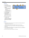
013121110987654321
~100-240
V
47-63
Hz
560
Watts
To avoid electric shock
the power cord protective
grounding conductor
must be connected to
ground. No operator
serviceable components
inside. Do not remove
covers. Refer servicing
to qualified personnel.
WARNING
!
LINE
OUT
PARALLEL PORT
COM 1 VIDEO
KEYBOARD
MOUSE
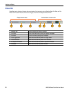
To enable or disable the LAN, see
enabling your LAN and connecting to a network
in your manual.
LPT
MIC
LINE
IN
USB
Ch 1 Digital Data OutCh 2 Digital Data Out
013 12 11 10 9 8 7 6 5 4 3 2 1
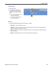
Ch 2
Add Input
Ch 1
External
Clock Input
Oscillator
Output
Reference
Clock Input
10 MHz
Reference Output
0.8 V p-p
50
1 V Max
50
3 V Max
50
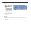
1
2
3
4