


Rear Panel
12 AWG5000 Series Quick Start User Manual
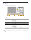
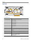
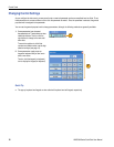
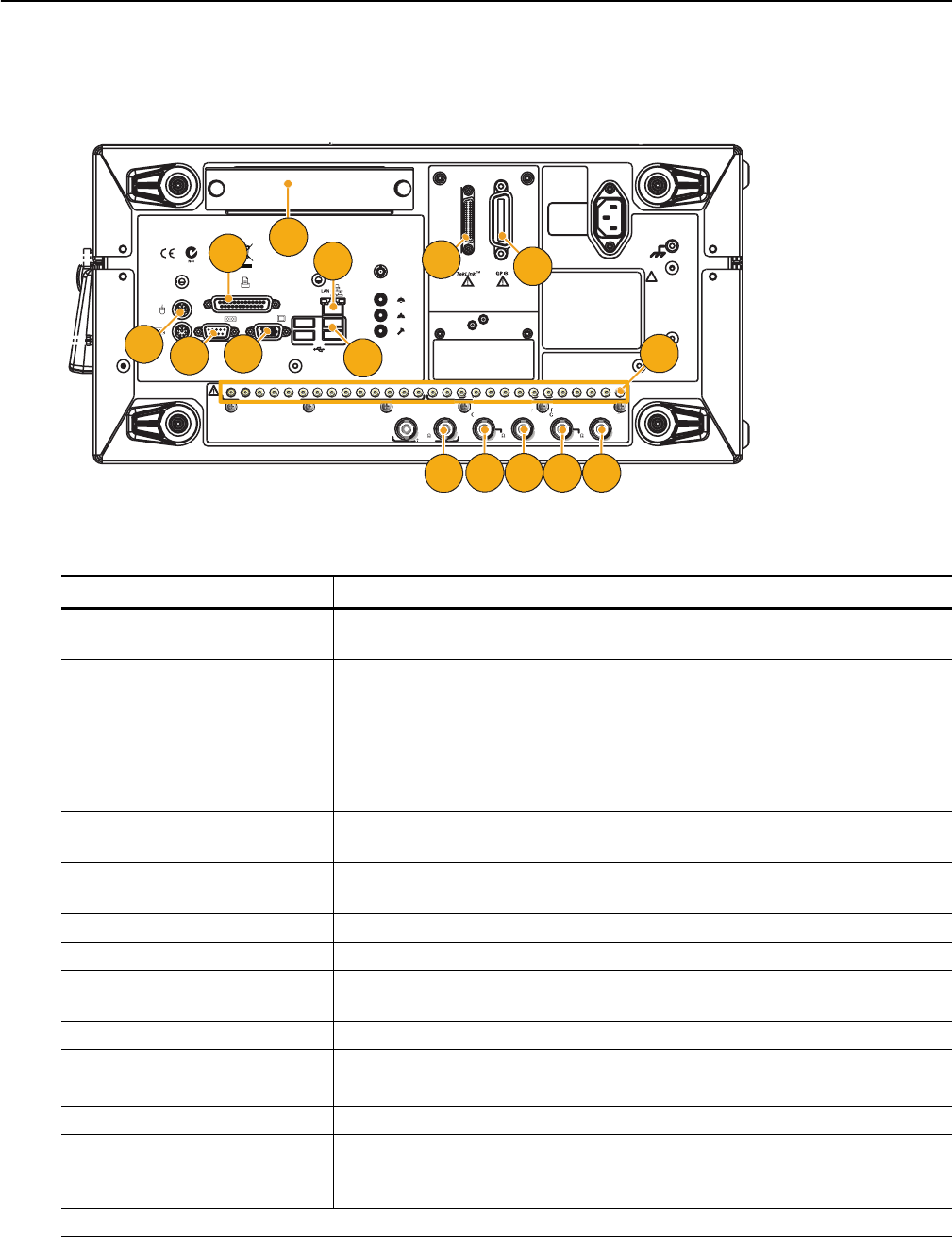
Rear Panel
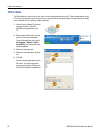
Rear Panel Connectors
Connector Description
1. 10 MHz Reference Output Output connector for 10 MHz reference clock signal
Connector Type: BNC
2. Reference Clock Input Input connector for external reference clock
Connector Type: BNC
3. Oscillator Output Output connector for internal oscillator
Connector Type: BNC
4. External Clock Input Input connector for oscillator input
Connector Type: BNC
5. Add Input Add external signal to the output signal of arbitrary waveform generator
Connector Type: BNC
6. GPIB Use the GPIB connector to connect the instrument to a GPIB controller for GPIB opera-
tion.
7. LAN Use the RJ-45 connector to connect the instrument to a network.
8. Parallel Port Use the parallel port (Centronics) to connect a printer or other device.
9. USB Use the USB connectors to connect a USB mouse, keyboard, or other USB device to the
instrument.
10. Video Use the Video port to connect a monitor for extended desktop operation.
11. COM1 Use the COM1 serial port to connect to other devices through the serial port.
12. PS-2 connector Use the PS-2 connectors to connect a PS-2 keyboard or mouse to the instrument.
13. Removable HDD Removable hard disk drive to secure data
14. Digital Data Out Use these connectors to output digital data. To enable digital data output, option 03 must
be installed in the AWG5002 or AWG5012.
Connector Type: SMB
15. This connector is not supported.
013 12 11 10 9 8 7 6 5 4 3 2 1
~100-240
V
47-63
Hz
560
Watts
To avoid electric shock
the power cord protective
grounding conductor
must be connected to
ground. No operator
serviceable components
inside. Do not remove
covers. Refer servicing
to qualified personnel.
WARNING
!
LINE
OUT
PARALLEL PORT
COM 1 VIDEO
KEYBOARD
MOUSE
To enable or disable the LAN, see
enabling your LAN and connecting to a network
in your manual.
LPT
MIC
LINE
IN
USB
Ch 1 Digital Data OutCh 2 Digital Data Out
013 12 11 10 9 8 7 6 5 4 3 2 1
Ch 2
Add Input
Ch 1
External
Clock Input
Oscillator
Output
Reference
Clock Input
10 MHz
Reference Output
0.8 V p-p
50
1 V Max
50
3 V Max
50
4
13
8
7
14
12
11
10
15
6
3
2 1
5
9