Control Panel
AWG5000 Series Quick Start User Manual
13
Control Panel
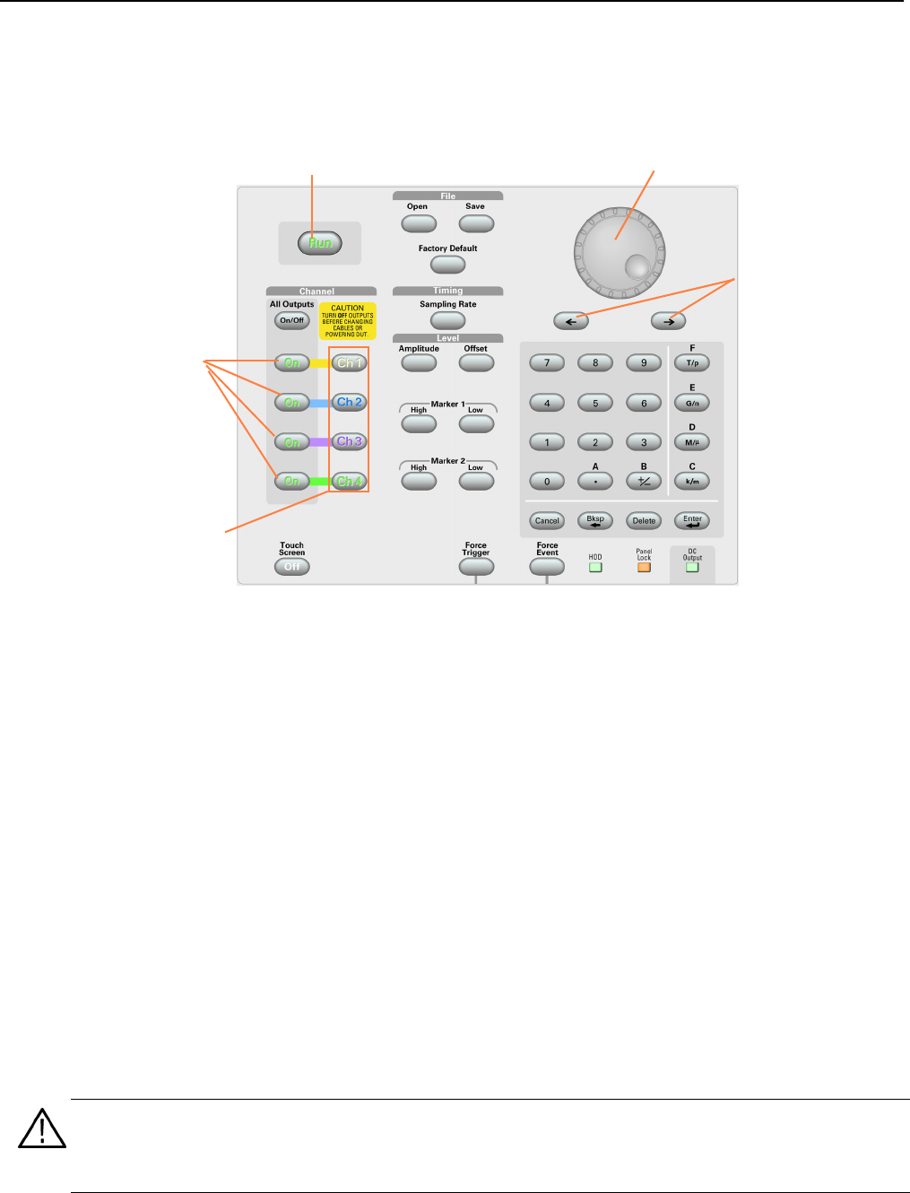
The following figure shows the front panel controls of a four channel model:
Run. The Run button is used to start and stop the signal generation. If the signal is being generated, the LED indicator
lights up. To output the signal through the output connectors, you must push the front-panel All Outputs On/Off button or
the Channel Output On button.
Touch Screen Off. When the Touch Screen is on, you can use your finger or stylus to control the screen interface. The
LED is lit while the Touch Screen interface is disabled.
File Open/Save. When the Open or Save button is pushed, the corresponding dialog box is displayed. You can load or
save a setup (*.AWG) file using this dialog box.
Factory Default. When this button is pushed, the specified default setups are recalled. See page 32 for details on default
setups.
Timing – Sampling Rate. When you push this button, the sampling rate parameter in the Settings window is selected.
Sampling Rate is common to each channel. See page 26 for Settings window.
Channel Select. These buttons are used to select a channel that you want to interact with. If a channel select button on
the front panel is pushed, the selected channel page in the Settings Window will be activated.
Channel Output On. These buttons are used to enable/disable the channel output. If the output is in the On state, the
LED is turned on.
Run button
Channel Output On
button
Channel Select
button
General Purpose knob
Digit Selection
keys
CAUTION. Do not connect a DUT (Device Under Test) to the front-panel signal output connectors when the instrument
signal outputs are on.
Do not power on or off the DUT when the arbitrary waveform generator signal outputs are on.


