


Adjustment Procedures
6–6
VITS100 NTSC VITS Inserter Instruction Manual
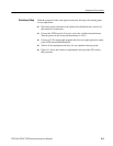
Television Test Signal Generator
VITS Inserter
Waveform/Vector Monitor
Test Signal
Program In Program Out
CH A input
75 W
Terminator
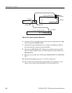
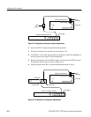
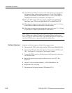
Figure 6–2: A setup for genlock adjustments
6. Connect a 75 W coaxial cable from the television test signal generator output
to the VITS inserter PROGRAM IN.
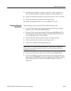
7. Adjust R30, Program Blanking DC Level Adjust, for blanking at 0 IRE on
the waveform/vector monitor waveform graticule.
8. Check that the PROGRAM OUT blanking level matches the trace position
when no signal is applied (remove and then replace the coaxial cable to the
PROGRAM IN).
9. Move the coaxial cable from VITS inserter PROGRAM OUT to MONITOR
OUT.
10. Check that the blanking level is 0 V "10 mV (3 minor div).
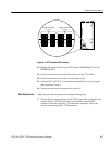
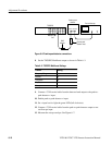
11. Set S1 VITS selection dual-inline-package (DIP) switch segments 1 and 4
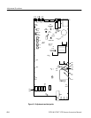
closed, 2 and 3 open (0110). See Figure 6–3 for the location of S1.