


Theory of Operation
4–4
VITS100 NTSC VITS Inserter Instruction Manual
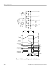
The Input Buffer, U42, also drives the genlock analog-to-digital converter
(ADC), U43. The ADC also has AGC and is clamped with “synctip” and
“backporch” signals, which provide the timing.
The clamped and AGC’d video is then routed through an anti-aliasing filter (L1,
C19, C20, and C21), and then reinput to the ADC where it is digitized. The
digital output is input to a PAL, U41. where it is inverted and latched. The signal
“sis_tm” from the genlock ASIC, on diagram 4, holds the same sample across
the bottom of sync to block Sound-in-Sync pulses from upsetting the genlock
circuitry.
Diagram 4. The output data from the PAL on diagram 3 is input to the Genlock
ASIC, U29, which has RAM, counters, decoders, and the other genlocking
circuitry. Composite sync is routed to the genlock ASIC through a PAL, U70.
The genlock ASIC uses the composite sync to roughly position the horizontal
and vertical counters.
The Genlock Processor, U35, is an 8 MHz Z80 that calculates the SCH of the
incoming video in order to determine the correct color framing. The processor
uses the digitized color subcarrier burst to determine the tangent of the phase
angle between the system clock and the burst. This tangent is used to look up the
arctangent (that is, the angle itself), which is stored in a PROM, U33. The angle
is used as a correction to the system clock, on diagram 6, to form a phase-locked
loop.
Diagram 6. The correction is an 8-bit word which is sent to DAC, U59. The
output of the DAC is integrated by an operational amplifier, U61A and C46. U60
is an analog switch that is used to short the integrator when searching for
genlock and to change the loop characteristics once lock is securely acquired.
The processor also increases loop gain once lock has been acquired and enables
the Genlock ASIC to output a frame reset pulse to align the test signal counters
with the genlock counters.
Y39 is the clock for the genlock processor (NOT the system clock). U31 is a
hardware watchdog that resets the processor if it fails to receive an “awake”
signal from the processor within the right amount of time. U38 latches control
signals “glk/int
” and “acq/hold” for U60, an analog switch, and the signal
“locked” to signify that genlock has been achieved. Counter/Timer U30 is used
to distinguish between even and odd fields of video.
Genlock sub-clock cycle timing can be adjusted up to 90
d
with S7. The VITS
signals are timed to program video input at the factory and should not need
adjustment.
S8 is a diagnostics switch; see the Maintenance section for details.