


Maintenance
VITS100 NTSC VITS Inserter Instruction Manual
7–13
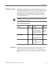
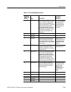
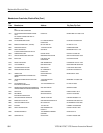
Table 7–3: The User Diagnostics (Cont.)
Diagnostic
Switch (S8)
Setting
Test Result
Indication
DescriptionTest
4 CTC Test Sets up the Counter Timer Chip
(CTC, A1U30), and checks to see
that the timers can generate inter-
rupts. Each of the four CTC sections
should interrupt after the 4096
processor clock cycles. If any CTC
section does not interrupt within the
allocated time, the test fails. This
test runs once during power-up
diagnostics.
In the event of fail-
ure, the UNLOCKED
LED lights and the
instrument does not
lock to program (in-
put) video.
5 Not Used
6 Not Used
7 Port test Used to check the data and load
paths connected to the I/O ports.
Counts from 0–255 on the I/O ports
(the ED0–ED7 bus) of the micropro-
cessor system.
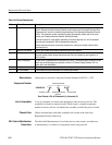
ED0–ED7 bus
should show a binary
count pattern when
viewed with an oscil-
loscope
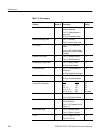
8 VCO DAC test Used to check the VCO DAC and
Integrator. Generates a field rate
ramp at the VCO DAC for checking
the genlock DAC.
Ramp may be
viewed at A1J12–2.
9 Sampler test 1 Used to check the Genlock Acquisi-
tion circuitry. This test acquires a
sample of sync and burst via the
genlock input and then reconstructs
the sampled sync and burst at
equivalent time through the VCO
DAC A1J12–2. A1C46 (schematic 6)
must be shorted out for this test.
A Sampler test 2 Sets up the genlock acquisition
system to sample incoming video
continuously. Used for checking
acquisition timing.
Use an oscilloscope
to check for correct
genlock timing
pulses on CTC
A1U30 pins 20–23.
Trigger on input
video.
B Not Used
C Not Used
D Not Used
E Not Used
F Not Used