Operating Basics
2–6
VITS100 NTSC VITS Inserter Instruction Manual
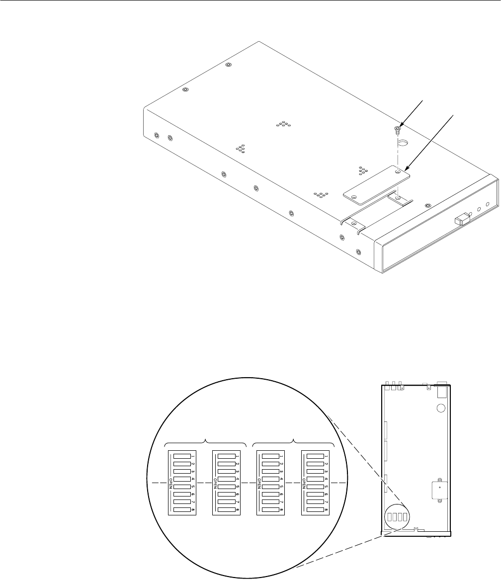
Screws (2)
Cover
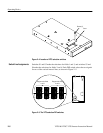
Figure 2–4: Location of VITS selection switches
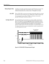
Switches S1 and S2 make the selections for fields 1 and 3, and switches S3 and
S4 make the selections for fields 2 and 4. Each DIP switch selects the test signals
for two of the vertical interval lines, as shown in Figure 2–5.
Program color fields
1 and 3
Program color fields
2 and 4
Line 18Line 17
Line 20Line 19
S1 S2 S3 S4
Line 18Line 17
Line 20Line 19
Figure 2–5: The VITS selection DIP switches
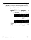
Switch/Line Assignments


