


Performance Verification
VITS100 NTSC VITS Inserter Instruction Manual
5–3
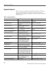
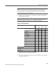
Table 5–1: Equipment Required (Cont.)
Item ExampleRequirements
75 W Feed-Through Terminator BNC-type, accuracy of 0.2%. Tektronix part number 011-0103-02
BNC Adaptor Female-to-female Tektronix part number 103-0028-00
75 W BNC Cables (five) 42 in coaxial cables, male BNC ends Tektronix part number 012-0159-00
Precision 50 W BNC cables (two) Male BNC ends Tektronix part number 012-0482-00
50 W to 75 W Minimum Loss Attenuator BNC connectors. Tektronix part number 011-0057-01
Verification Procedure
This is a step-by-step procedure that begins with switching the instrument on.
While waiting for the VITS inserter to warm up, store the signal references in the
video measurement set.
This is a preparatory step that ensures all equipment will be ready to operate
when you begin to verify VITS inserter performance.
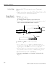
1. Connect the VITS inserter power cord to the variable autotransformer.
2. Set the autotransformer for 115 volts. (Set it to 230 volts for systems
powered with 220/240 volt sources.)
3. Turn on the autotransformer, test signal generator, and video measurement
set.
4. Turn the VITS inserter power on.
5. Allow all equipment to warm up for the period prescribed by the equipment
manufacturers (a minimum of 20 minutes).
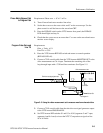
The video measurement set stores reference signals for later comparison. The
following steps store the references for these comparisons. The test signal is the
NTC7 composite waveform from the television test signal generator. See
Specifications for more information on this signal.
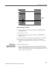
NOTE. Steps 1 through 8 store reference signals in the video measurment set
(VM700A) that are later recalled for signal element comparisons.
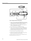
1. Connect a 75 W coaxial cable from the output of the television test signal
generator to the video measurement set Ch A input. Terminate the open side
of the loop-through input with a 75 W end-line terminator.
Power Up
Test Signal References