


Performance Verification
VITS100 NTSC VITS Inserter Instruction Manual
5–7
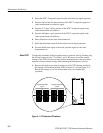
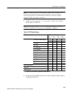
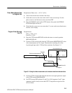
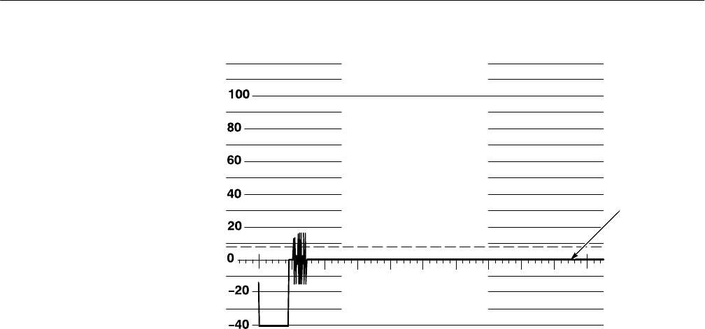
IRE
Blanking
level
Figure 5–3: Blanking level at 0 IRE
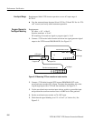
6. Move the 75ĂW coaxial cable from the VITS inserter PROGRAM OUT to
the MONITOR OUT.
7. Repeat steps 3, 4, and 5.
8. Move the 75 W coaxial cable from the VITS inserter MONITOR OUT to
PROGRAM OUT.
9. Use the waveform/vector monitor line select to display line 17 for all fields.
10. Check that the inserted 0% black (line 17 fields 1 and 3) matches the
blanking level of the passed lines (line 17 of fields 2–4) "3 mV (1 minor
division).
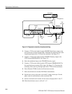
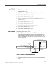
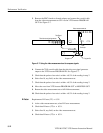
Requirement: Phase match "1°
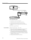
1. Connect a 75 W coaxial cable from the Test Signal Generator/Sync Pulse
Generator (TSG/SPG) subcarrier output to the waveform/vector monitor Ext
CW Ref. Terminate the remaining side of the loop-through input with a 75 W
end-line terminator. See Figure 5–4.
Phase Match of
Inserted Test Signal to
Program Video Channel