Adjustment Procedures
6–12
VITS100 NTSC VITS Inserter Instruction Manual
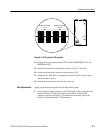
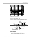
17. Adjust R210 and C165 for a display on the Test Oscilloscope that matches
the sweep envelope to the previous waveform ± 4.3 mV from 2 MHz to
6 MHz (second marker to fourth marker) and ± 12.9 mV from 6 MHz to
10 MHz (fourth marker to sixth marker). See Figure 6–7.
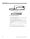
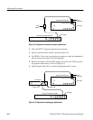
18. Move the 75 W coaxial cable that connects to the Peak-to-Peak Detector
Head Input from VITS inserter PROGRAM OUT to MONITOR OUT.
19. Check that the sweep envelope matches that observed in step 17, ± 4.3 mV
from 2 MHz to 6 MHz (second marker to fourth marker)
20. Check that the sweep envelope matches that observed in step 17, ± 12.9 mV
from 6 MHz to 10 MHz (fourth marker to sixth marker).
NOTE. If the VITS inserter does not meet frequency response specifications in the
5.5 to 10 Mhz range, adjust L12 and L13 for optimum flatness in that range.
These two coils are sealed with a drop of glue during manufacture; adjust them
only if the VITS Inserter is operating outside of specifications.
Adjust the oscillator frequency with the following procedure.
1. Disconnect the 75 W coaxial cable from the VITS inserter PROGRAM IN.
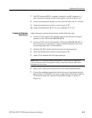
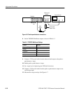
2. Connect the X10 probe from the Frequency Counter input to VITS inserter
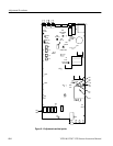
TP 11. See Figure 6–1 (on page 6–4) for test point location.
3. Connect the WWV signal to the other input of the Frequency Counter and
set it for Ratio A/B.
4. Remove the plastic plug from the oscillator cover to reveal C19. See
Figure 6–1.
5. Adjust C19 for an oscillator frequency of 28.636364 MHz ±1 Hz.
6. Replace the C19 access plug.
7. Disconnect the X10 probe from the VITS inserter TP 11.
Oscillator Adjustment


