VITS100 NTSC VITS Inserter Instruction Manual
4–1
Theory of Operation
This section of the manual begins with a functional description of the circuitry.
This brief discussion is followed by a more detailed set of circuit descriptions
that take you to the individual component level of the schematic diagrams.
Functional Description
Program In. The program input is buffered and clamped. The clamped program
video drives the Sync Stripper that strips off composite sync and generates the
backporch timing for the Clamp.
Genlock. The genlock calculates the SCH phase of the incoming video to
determine the correct color framing. A phase-locked loop is used to control a
voltage-controlled oscillator (VCO). When the VITS inserter is genlocked, a
frame reset pulse is generated to align the test signal counters with genlock
counters.
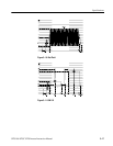
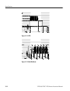
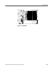
Test Signal Generation. The VITS100 NTSC VITS Inserter can insert four lines
on odd and even fields. Signals are selected with four DIP switches on the main
circuit board. The lines from the switches are multiplexed and form one of the
inputs to the Test Signal Generator.
Test signals are generated by clocking data from PROMs to a digital-to-analog
converter (DAC) at an 8
FSC
rate. The output of this DAC is filtered and buffered
before driving the VITS Inserter.
Program Out. The VITS inserter video signal output can be from any of three
sources: clamped video through the instrument, VITS signals inserted on one of
the four VITS lines, or the bypassed program line. The bypassed program line
has a built-in delay line to maintain the precise time relationship between the
processed and bypassed video.
Remote Control. Remote control is limited to ground-closure bypass control and
the power, unlocked, and bypass indicator lines.
Power Supply. The power supply, located on the Inserter board, is a current-mode
controlled, discontinuous, flyback, switching power supply. The current output is
distributed among the four supplies.


