


Operating Basics
VITS100 NTSC VITS Inserter Instruction Manual
2–3
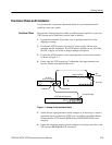
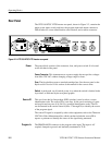
The PROGRAM OUT connector is the program video output. Output video can
have user-selected VITS inserted on selected lines. If the instrument cannot lock
to the program input video signal, or if power fails, the program automatically
bypasses the VITS inserter processing circuitry; the input signal is then routed
through a delay line, with a delay equivalent to the processing delays of the
instrument, to PROGRAM OUT. Matching the delay eliminates timing errors
whenever the VITS inserter must enter bypass mode.
This connector provides the same output as the PROGRAM OUT connector,
except that the MONITOR OUT is not in the bypass signal path. This means
that —during loss of genlock or activation of the bypass mode —the monitor
output will still contain any inserted VITS. There is no output from this
connector if power is lost.
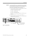
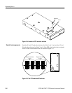
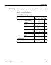
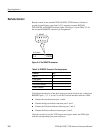
This 9-pin connector enables ground-closure remote control of bypass mode. In
addition, control lines that parallel the three front panel indicators (POWER,
BYPASS, and UNLOCKED) are brought out to this connector.
Insertion Options
You can configure the VITS inserter to insert test signals, pass existing video,
insert or pass VIRS, or insert a source ID on lines 17, 18, 19, and 20 of both the
even and odd fields of NTSC video.
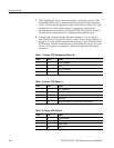
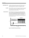
The standard VITS100 NTSC VITS Inserter can insert the following test signals
into the vertical interval:
H FCC Color Bars H FCC Composite
H FCC Multiburst H NTC7 Combination
H NTC7 Composite H VIRS
H 7.5% Black H 0% Black
H Multipulse H SIN X/X
H Red Field H 50% Gray
You can find descriptions of these waveforms in the Specifications section of this
manual. If your instrument contains Option 1J, Option 1M, or Option 2, see
Appendix A: Options for descriptions of the optional signals.
Program Out
Monitor Out
Remote Connector
Inserting Test Signals