


Performance Verification
VITS100 NTSC VITS Inserter Instruction Manual
5–5
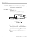
NOTE. The settings of S1-S2-S3-S4 dictate the signals, lines, and fields for the
VITS insertion program. Because the instrument may contain a required
operating program, it is essential that the switches be reset to the original
settings when this procedure is completed.
2. Set DIP switch S1, segments 1, 2, 3, and 4 (line 17, field 1) for 0% Black
(0110) signal; see Table 5–2.
NOTE. Switch settings in Table 5–2 are for standard instruments. Signal, line,
and field assignments for the options are in Appendix A: Options.
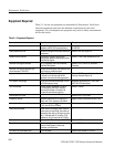
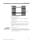
Table 5–2: DIP Switch Settings
VITS inserter Action DIP Segment Settings*
1 (5) 2 (6) 3 (7) 4 (8)
Insert Test Signals:
se e er se
0 1 1 0
0% Black (u
se
e
ith
er
se
tting)
1 0 0 1
7.5% Black 1 1 1 0
50% Gray 1 1 0 1
FCC Color Bars 0 0 0 0
FCC Composite 1 0 0 0
Multipulse 0 1 0 0
Multiburst 0 1 0 1
NTC 7 Composite 1 0 1 0
NTC 7 Combination 0 0 0 1
Red Field 1 1 0 0
SIN X/X 0 0 1 0
VIRS 1 0 1 1
Pass Program Video 1 1 1 1
Auto VIRS 0 0 1 1
Insert Source ID 0 1 1 1
* 1 signifies an OPEN switch; 0 signifies a closed switch
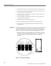
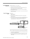
3. Set all the remaining DIP switches to the “pass incoming” position, which is
all segments open (1111).