Performance Verification
VITS100 NTSC VITS Inserter Instruction Manual
5–11
Requirements:
Differential gain v 0.2%
Differential phase v 0.2_
1. Select Relative to Ref Diff Phase + Gain on the video measurement set.
2. Check that the differential gain is v 0.2%.
3. Check that the differential phase is v 0.2_.
4. Move the coaxial cable from the VITS inserter MONITOR OUT to the
PROGRAM OUT.
5. Check that the differential gain is v 0.2%.
6. Check that the differential phase is v 0.2_.
7. Select line 18, any field, on the video measurement set.
8. Check that the differential gain is v 0.2%.
9. Check that the differential phase is v 0.2_.
Requirement: Ratio + 100% "0.5%.
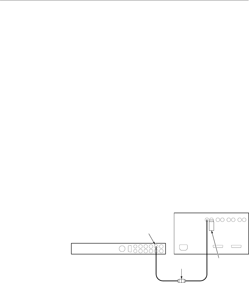
1. Use two 75 W coaxial cables, joined with a BNC female-to-female adaptor to
connect the test signal generator (TSG) to the video measurement set Ch A
Input. Terminate the remaining side of the Ch A loop-through input with a
50 W end-line terminator. Select the NTC7 Composite test signal from the
TSG. See Figure 5–6.
Television test signal generator
Video measurement set
BNC
Adapter
Test Signal
75ĂW
Terminator
Figure 5–6: Setting up for pulse-to-bar measurement
2. Observe and remember the pulse-to-bar ratio on the video measurement set
screen.
Differential
Gain and Phase
Pulse-to-Bar Ratio
