


Performance Verification
VITS100 NTSC VITS Inserter Instruction Manual
5–23
3. Set the waveform/vector monitor line select to line 19, all fields.
4. Check for VIRS. If there is a signal other than VIRS, you will need to either
reprogram the TSG/SPG VITS signals or find a VIRS signal on another line.
VIRS is required on both fields.
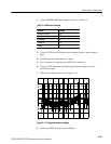
5. Set VITS selection switch S2, segments 1 through 4, to 0011 (segments 1
and 2 closed, 3 and 4 open).
6. Confirm that S4 segments 1, 2, 3, and 4 are all open (1111).
7. Turn off the TSG/SPG power switch.
8. Using the waveform/vector monitor line and field selection switches, verify
that the VIRS signal is on field 1 and missing on field 2.
Requirement: 16 asserted bits ^ 0.5 V
1. Check and note the position of all rear-panel SOURCE ID switches. These
switches determine the source identification output by the VITS inserter;
restore the original settings after completing this check.
2. Set all 16 switches to the down position.
3. Set VITS inserter line/field selection switch S1, segments 5 through 8, to
0111 (segment 5 closed and segments 6, 7, and 8 open).
4. Select line 18, field 1, on the waveform/vector monitor.
5. Check that there are 16 positive excursions (from 0 V) of approximately
0.5 V. (Instruments with serial numbers below B020425 will have excursions
of approximately 0.7 V.)
6. Switch the waveform/vector monitor Field selection to field 2 and check that
the source ID signal is not present.
Requirement: Grounding pin 6 of the rear-panel REMOTE connector forces the
instrument into bypass mode.
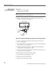
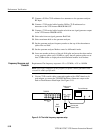
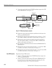
1. Connect a 75ĂW coaxial cable from the VITS inserter PROGRAM OUT to
the waveform/vector monitor Ch A input. Terminate the remaining side of
the loop-through input with a 75ĂW end-line terminator.
2. Set the waveform/vector monitor line select to line 19, field 1.
3. Check that the VIRS signal is displayed on the waveform/vector monitor.
4. Use a short piece of wire to short pin 6 of the rear-panel REMOTE connector
to ground. (Pins 1, 4, and 9 of the REMOTE connector are ground.)
Source ID
Remote Control