Performance Verification
5–22
VITS100 NTSC VITS Inserter Instruction Manual
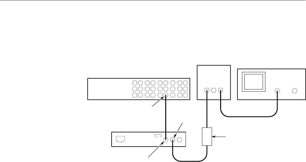
9. Connect the coaxial cable from the TSG/SPG multiburst output to the VITS
inserter PROGRAM IN. See Figure 5–12.
VITS Inserter
TSG/SPG
Test oscilloscope
Peak-to-peak
detector
Multiburst
Out
Program In
Program Out
Peak-to-peak
detector head
OUTPUTINPUT
Figure 5–12: Measuring frequency response
10. Connect the coaxial cable from the peak-to-peak detector head input to the
VITS inserter PROGRAM OUT.
11. Check that the sweep envelope matches the previous waveform " 4.3 mV
from 2 MHz to 6 MHz (second marker to fourth marker). See Figure 5–11.
12. Check that the sweep waveform top matches the waveform measured in
step 7 (the “pattern”) within " 12.9 mV from 6 MHz to 10 MHz (fourth
marker to sixth marker). See Figure 5–11.
13. Move the Peak-to-Peak Detector Head and cable from PROGRAM OUT to
MONITOR OUT.
14. Check that the sweep envelope matches the pattern " 4.3 mV from 2 MHz
to 6 MHz (second marker to fourth marker). See Figure 5–11.
15. Check that the sweep envelope matches the pattern " 12.9 mV from 6 MHz
to 10 MHz fourth marker to sixth marker). See Figure 5–11.
Requirement: Proper VIRS insertion
1. Connect a 75 W coaxial cable from the TSG/SPG black burst output to the
VITS inserter PROGRAM IN.
2. Connect a 75 W coaxial cable from the VITS inserter PROGRAM OUT to
the waveform/vector monitor input. Terminate the remaining side of the
loop-through connector with a 75 W end-line terminator.
Auto VIRS Insertion


