Performance Verification
5–6
VITS100 NTSC VITS Inserter Instruction Manual
Requirement: Stable VITS inserter operation over an AC input range of
90–250 V
H Vary the autotransformer between 90 and 125 Vac (210 and 250 Vac for “220
volt” sources) and verify stable instrument operation.
Requirements:
DC offset + 0V "10 mV
Insertion transients v10 mV
DC matching of inserted test signal to program signal "3mV
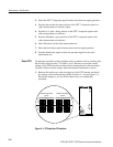
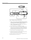
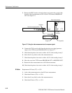
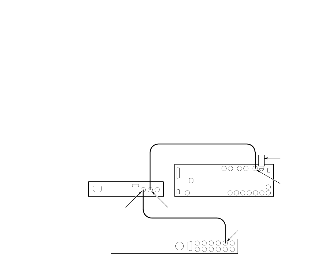
1. Connect a 75 W coaxial cable from the television test signal generator signal
output to the VITS inserter PROGRAM IN. See Figure 5–2.
Television test signal generator
VITS Inserter
waveform/vector monitor
Test Signal
Program In
Program Out
CH A input
75 W
Terminator
Figure 5–2: Measuring VITS on a waveform/ vector monitor
2. Connect a 75ĂW cable from the VITS inserter PROGRAM OUT to the
waveform/vector monitor CH A Input. Terminate the remaining side of the
loop-through input with a 75ĂW end-line terminator. See Figure 5–2.
3. Use the waveform/vector monitor input selector switch to ground the input
and position the waveform monitor trace on 0 IRE level of the graticule.
4. Set the waveform/vector monitor to Ch A DC input.
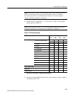
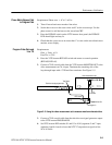
5. Check that the signal blanking is at 0 V "10 mV ("3 minor div). See
Figure 5–3.
Line Input Range
Program Channel to
Test Signal Matching


