


Operating Basics
2–8
VITS100 NTSC VITS Inserter Instruction Manual
Remote Control
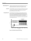
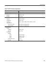
Remote control in the standard VITS100 NTSC VITS Inserter is limited to
ground-closure Bypass control and (+5 V) outputs for remote BYPASS,
UNLOCKED, and POWER indicator lights. See Figure 2–6 and Table 2–3 for
the rear-panel REMOTE connector pin assignments.
VITS Inserter
51
96
REMOTE
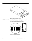
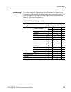
Figure 2–6: The REMOTE connector
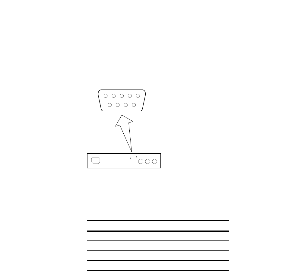
Table 2–3: REMOTE Connector Pin Assignments
Function Pins
Ground 1, 5
Force Bypass 6
BYPASS Indicator 2
UNLOCKED Indicator 7
POWER Indicator 3
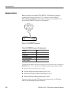
To duplicate the function of the front panel at a remote location, run a cable from
REMOTE pins 1, 2, 3, 5, 6, and 7 to an SPST switch and three indicator LEDs.
H Connect the switch between pins 1 and 6.
H Connect the Bypass indicator between pins 2 and 5.
H Connect the Unlocked indicator between pins 7 and 5.
H Connect the Power indicator between pins 3 and 5.
Close the switch to force the VITS inserter into bypass mode; the LEDs light
with the corresponding front-panel indicators.