


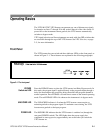
Operating Basics
2–2
VITS100 NTSC VITS Inserter Instruction Manual
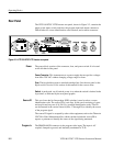
Rear Panel
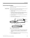
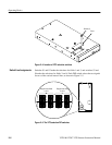
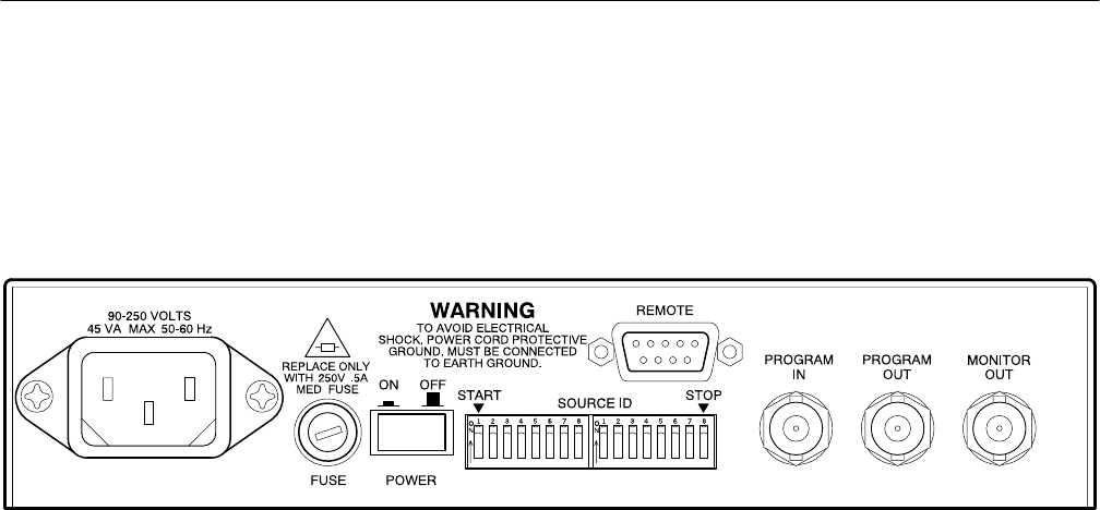
The VITS100 NTSC VITS Inserter rear panel, shown in Figure 2–2, contains the
mains power input, switch, and fuse; the program input and output connectors;
DIP switches for source identification code selection; and a remote connector.
Figure 2–2: VITS100 NTSC VITS Inserter rear panel
The power block consists of the connector, fuse, and power switch. It is located
on the left third of the panel.
Power Connector. This instrument uses a power supply that accepts line voltages
from 90 to 250 VAC without changing voltage ranges or fuses.
Fuse. The fuse holder accepts a standard cartridge fuse. See the rear panel or the
Replaceable Electrical Parts section of this manual for the correct value.
Switch. A push-push, on-off switch; power is on when the switch is latched in the
in position, as indicated by the rear-panel graphic.
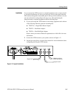
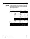
This set of two dual in-line package (DIP) switches is used to select a source
identification code. The source ID is a one-line, 16-bit word consisting of a start
and stop bit and any one of 16,384 (2
14
) possible identification codes. The ID
can be inserted in the vertical interval (lines 17 through 20) to identify the source
of the program signal.
The source ID signal is accepted by other video equipment, such as the Tektronix
VM 700A Video Measurement Set, which can then include the source ID in
reports or printouts to identify the source of the signal being measured.
The PROGRAM IN connector is the program video input. The input is AC
coupled, clamped to ground, and internally terminated in 75 W.
Power
Source ID
Program In