


Getting Started
1–4
VITS100 NTSC VITS Inserter Instruction Manual
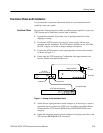
7. While watching the waveform monitor display, repeatedly press the VITS
inserter BYPASS switch to alternate between bypass and normal operating
modes. Confirm that the appearance of the vertical interval (that is, the “gap”
between the two visible fields) changes in appearance, indicating the
alternating presence and absence of inserted VITS. The change is easiest to
see when the test signal generator is outputting a Black Burst signal.
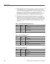
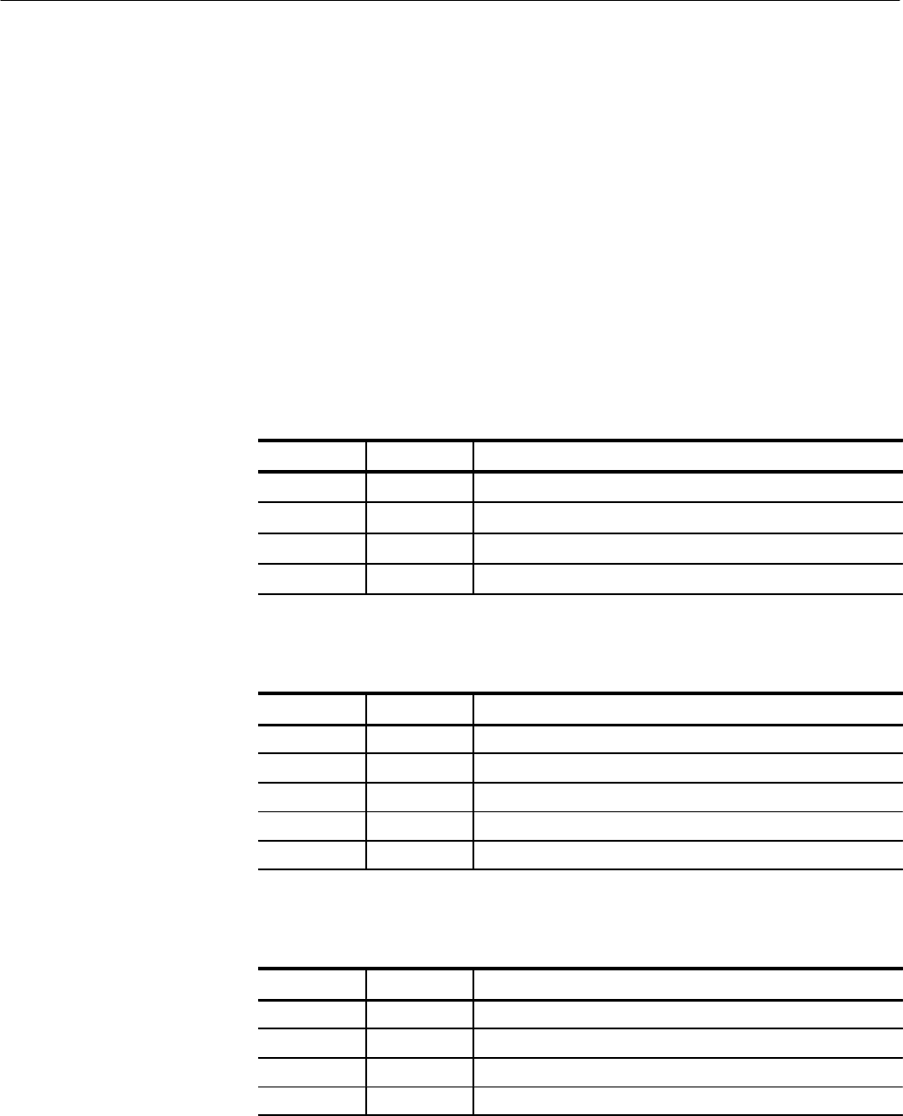
8. Configure the waveform monitor line-select feature to view one line at a
time. Check lines 17 through 20 of fields 1 and 2 for test signals. Tables 1–1
through 1–3 list the signals generated and inserted by a new VITS100 NTSC
VITS Inserter with the as-manufactured configuration. See the Specifications
Section of this manual or Appendix A: Options for diagrams of the signal
waveforms.
Table 1–1: Factory VITS, Standard and Option 1M
Field Line Signal
1 17 NTC7 Composite
1 19 VIRS
2 17 NTC7 Combination
2 19 VIRS
Table 1–2: Factory VITS, Option 1J
Field Line Signal
1 17 FCC Composite
1 19 Color Bars (No Setup)
1 20 Sin X/X
2 17 Multiburst
2 20 Red Field (modified Luminance and Chrominance)
Table 1–3: Factory VITS, Option 2
Field Line Signal
1 17 Cable Multiburst
1 18 FCC Composite
2 17 Cable Sweep
2 18 Sin X/X