


Performance Verification
VITS100 NTSC VITS Inserter Instruction Manual
5–9
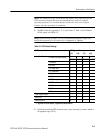
Requirement: Phase error + 0°"1° at F
SC
.
1. Turn off waveform/vector monitor line select.
2. Set the burst vector to the outer circle and 0° on the vectorscope. Use the
phase control to null the burst on the waveform CRT.
3. Press the BYPASS switch on the VITS inserter front panel; the BYPASS
LED should light and stay lit.
4. Check that the vector moves no more than 1° as seen on the waveform/vector
monitor vector display.
Requirements:
Gain + Unity "1%
Line Tilt v 0.5%
1. Press the VITS inserter BYPASS switch and return to normal operation
(BYPASS LED off).
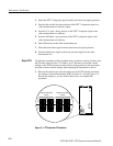
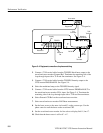
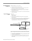
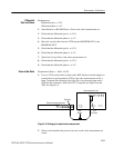
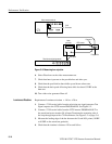
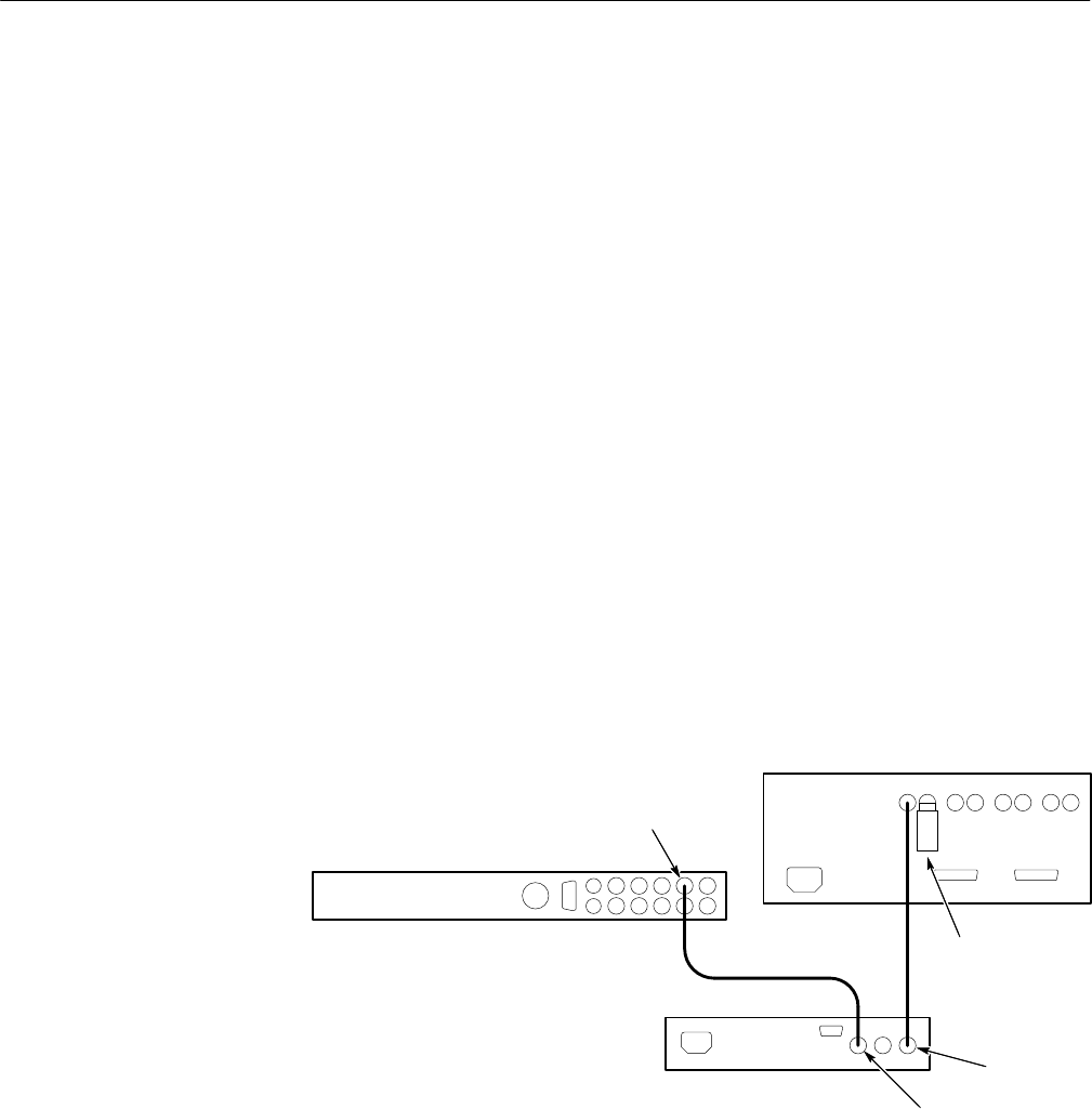
2. Connect a 75 W coaxial cable from the VITS inserter MONITOR OUT to the
video measurement set Ch A input. Terminate the remaining side of the
loop-through input with a 75 W end-line terminator. See Figure 5–5.
VITS Inserter
Television test signal generator
Video measurement set
Test Signal
75ĂW
Terminator
Program In
Monitor Out
Figure 5–5: Using the video measurement set to measure waveform characteristics
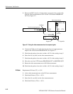
3. Connect a 75 W coaxial cable from the television test signal generator output
to the VITS inserter PROGRAM IN.
4. Set VITS inserter DIP switches S1 and S3 to 1010 (segments 5 and 7 open,
segments 6 and 8 closed) to insert the NTC7 Composite test signal on line
18 of all fields.
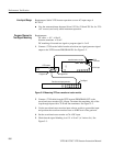
Phase Match Bypass Path
to Program Path
Program Video Gain and
Line Tilt