


VITS100 NTSC VITS Inserter Instruction Manual
2–1
Operating Basics
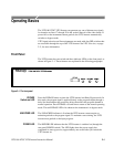
The VITS100 NTSC VITS Inserter can generate any one of thirteen test signals
for insertion on lines 17 through 20 in the vertical interval of the video frame. If
power fails or the instrument cannot genlock, the VITS inserter automatically
switches to bypass mode.
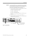
VITS signal selection and line assignments are made with four DIP switches that
are accessible through the top of the VITS inserter. See VITS Selection, on page
2–5, for more information.
Front Panel
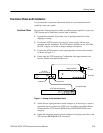
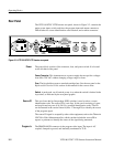
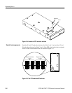
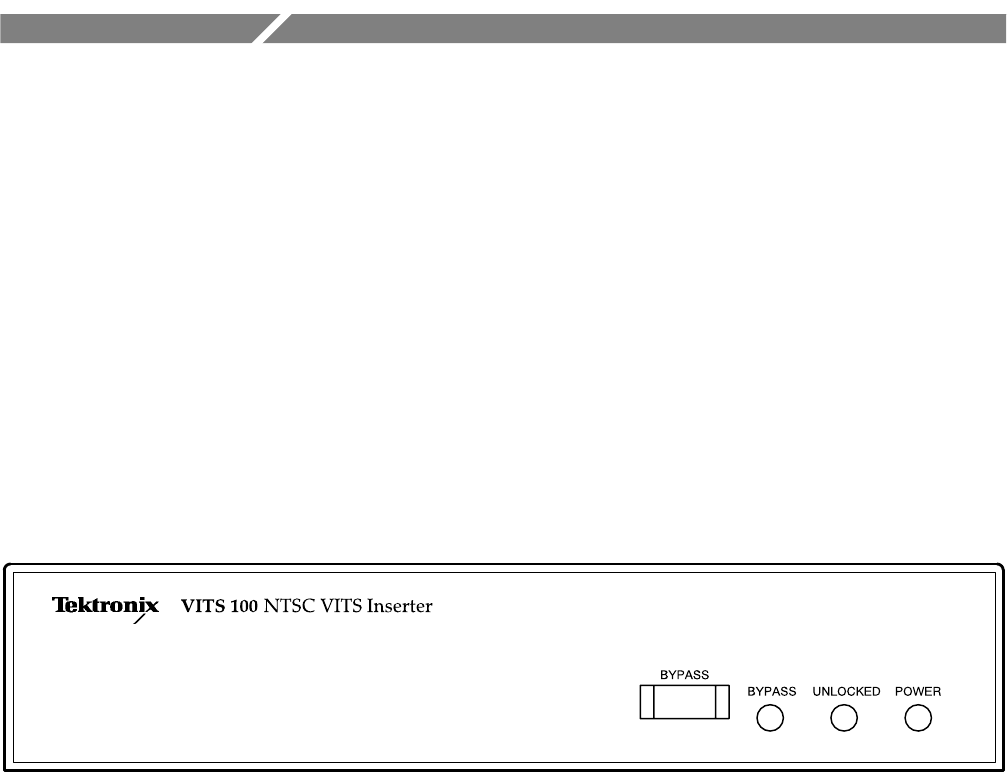
The VITS inserter has one switch and three indicator LEDs on the front panel, as
shown in Figure 2–1. These features are explained in the following paragraphs.
Figure 2–1: The front panel
Press the BYPASS button to place the VITS inserter into Relay Bypass mode. In
this mode, the program input is applied directly to the program output through a
delay line that matches the processing delays that affect the program channel in
normal operation. Press BYPASS a second time to return to the normal operating
mode. The red BYPASS LED is lit whenever the instrument is in bypass mode.
The UNLOCKED indicator is lit when the VITS inserter cannot acquire or
maintain genlock to the program signal. To maintain correct timing, the VITS
inserter must genlock to the input program.
The POWER LED indicates that the VITS inserter is switched on (through the
rear-panel POWER switch). The LED lights when the power supply has
completed its start-up process, approximately one second after you switch the
VITS inserter on.
BYPASS
Switch and LED
UNLOCKED LED
POWER LED