


Theory of Operation
VITS100 NTSC VITS Inserter Instruction Manual
4–9
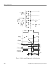
The Pulse Width Modulator, U78, is a current-mode controller. Using inputs
from the primary circuit and the +5 V output, it varies the width of the pulse that
controls Q16. This pulse width variation regulates the secondary voltages
throughout variations in the input voltage, output load, and temperature. R163
senses the current in the primary winding of T1 and applies it to U78–3 as a
voltage.
At the start of the cycle a flip-flop within U78 turns Q16 and Q17 on. The
primary current, and therefore the voltage to pin 3, ramps up until the level is
sufficient to trip the internal comparator, which resets the flip-flop and terminates
the drive pulse to Q17, and the energy stored in the transformer transfers to the
secondary windings.
Line regulation is automatic and without voltage feedback. As the input voltage
increases, the slope of the ramp increases and the trip point is reached sooner,
creating a narrower pulse width.
Load regulation is accomplished by sensing the +5 V output, resistively dividing
it to 2.5 V, and comparing it to a 2.5 V reference to develop the error signal fed
back to the Pulse Width Modulator. U74 is a band-gap reference set to function
as an error amplifier with a 2.5 V internal reference. Pin 3 of U74 provides the
error signal that is coupled through U75, an opto-isolator, to U78.
If the load increases, the signal at U78, pin 2, drops in voltage, which causes
U78 to increase the pulse width and thus increase the current through T1. If the
load decreases, the +5 V increases momentarily and output pulse width
decreases. Q18 adds a portion of the timing ramp to improve noise immunity.
If the ramp voltage at U78, pin 2, reaches 1 V the output drive pulse ends and
Q16 and Q17 shut off. The maximum primary current in T1 is limited to about
1.5 A, which corresponds to a maximum power level of approximately 60 W.
U78, pin 1 is an indication of the peak current in T1. This voltage is fed to the
inverting input of U76 and compared to a fixed voltage set by divider R161,
R171, and R160. R171, an output power adjustment, is set so the trip point will
be approximately 70 W. If U78, pin 1 goes high enough to trip U76A, pin 1 low,
C99 starts to charge. If this condition persists long enough for the charge on C99
to reach 700 or 800 mV, Q18 turns on and applies the reference voltage directly
to U78, pin 3 to shut down the supply. In this condition the supply will
continuously cycle through kick start, current limit, and shutdown until the
problem is corrected.
Jumper P9 is included for troubleshooting; its removal disables the current limit
shutdown circuits.
Q16 is a high blocking voltage (1000V) power transistor. To prevent transistor
failure and ensure proper operation, its base must have a large forward current
during the on-time and a large momentary reverse current pulse during turn off.