


Adjustments
'< .C<61 =<@@6/92 6;7B?F
1
6@0<;;20A =9B4 3?<: =<D2?
@<B?02 /23<?2 =2?3<?:6;4 .;F .@@2:/9F
.17B@A:2;A<??2=.6?
17B@A6;4H2C29&A<=
&.D9.12HA<'./92
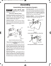
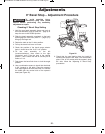
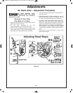
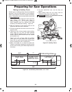
1. Pull up the bevel lock lever to unlock. Move the left
sliding fence fully to the left.
2. Tilt the saw assembly to the left
(counterclockwise) until it hits the 45° stop.
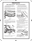
3. Place only the combination square’s head on the
saw’s table with its long flat side resting on the
table and its 45° side against the tilted blade.
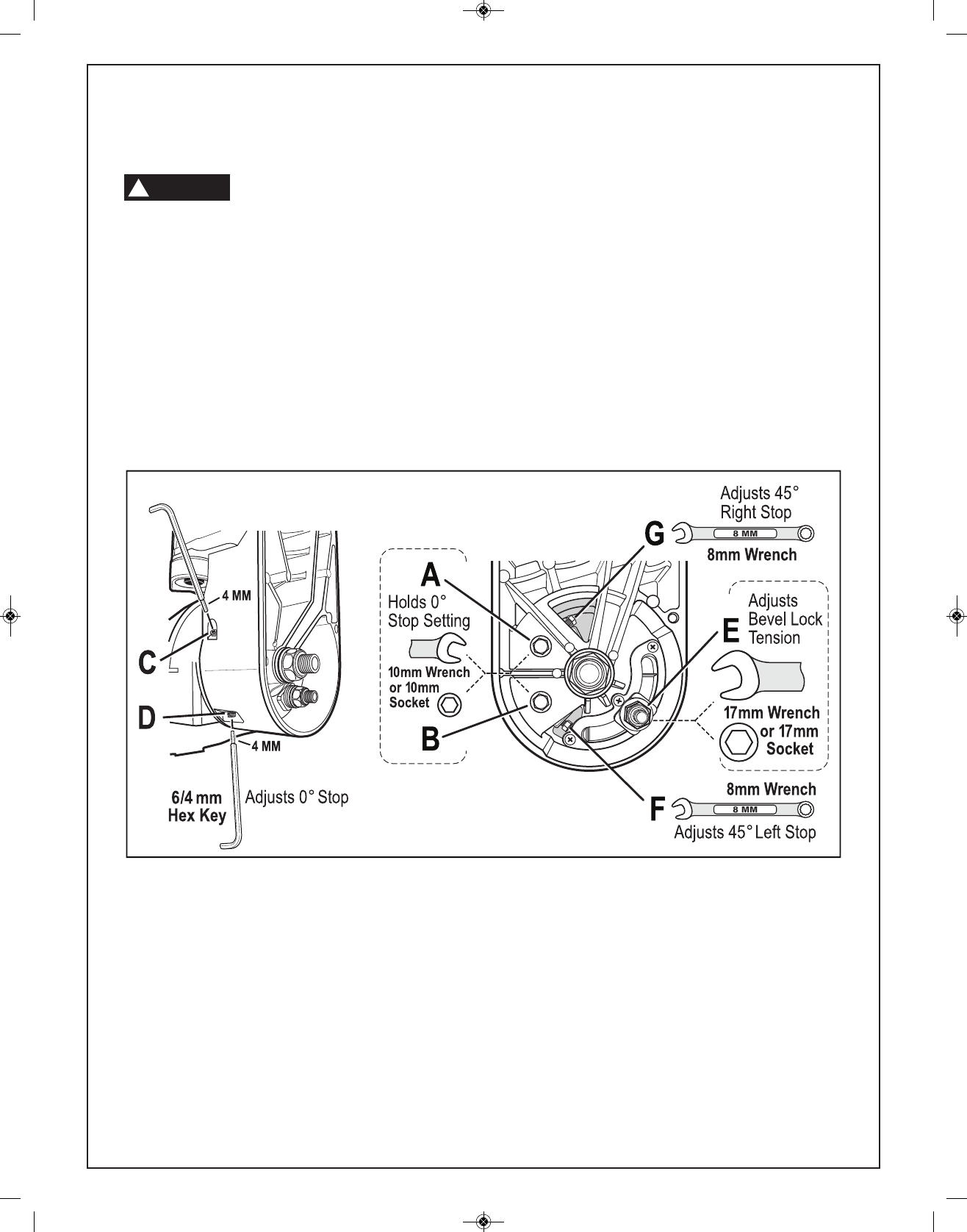
4. Place an 8mm open end wrench on bolt head “F”
(see Figure 25).
5. While turning bolt “F,” watch the blade tilt – turn “F”
until the saw blade plate is in full contact with the
4
5° side of the square’s head (see Figure 24).
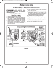
6. If needed, adjust bevel scale pointers (item 36 –
page 9) to be in line with the bevel scale’s 45°
lines. First, adjust right bevel pointer; then tilt saw
head to the right 45° stop position (see page 41 –
“Bevel Range 2 = 0-45° Right”) and adjust the left
bevel pointer. Tilt the saw head to the 0° position
– both pointers should be on the bevel scale’s 0°
lines.
7. Push down the bevel lock lever to lock at the
desired bevel angle.
*%""
!
H2C29&A<=J17B@A:2;A$?<021B?2
64B?2
Adjusting Bevel Stops
BM 2610007877 04-10:BM 2610007877 04-10.qxp 4/26/10 8:13 AM Page 24