


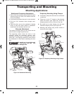
*5.AN@.&9612BAJ&.D2.AB?2@
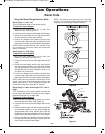
l A
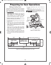
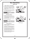
“slide cut” is made with the head assembly
unlocked and able to move away from the fence.
This movement is supported and precisely
controlled by the axial glide system. The
maximum cross-cutting capacity is utilized by
using this method.
l A slide cut is best used for cross-cutting
workpieces wider than can be done with a chop
cut – pieces wider than 5-1/2" and up to a
maximum width of 13-3/8" across.
")%=B99A52@.DA<D.?1 F<B
1B?6;4 . 0BA '52 /9.12 0.;
@B112;9F 096:/ B= <; A<= <3A52D<?8=6202 .;1
3<?026A@293A<D.?1F<B
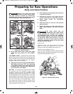
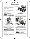
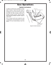
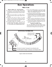
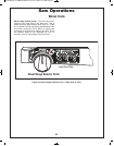
$?2=.?6;43<?&9612BA
1. Place the saw head in the UP position.
2. Disengage the mechanism lock lever (item 27 –
page 9) by pushing down on the finger tab. With
the head assembly in the UP position, move it fully
to the front and back to check that axial glide
system moves smoothly.
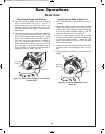
3. Properly position your workpiece and clamp it
firmly to the table and/or fence.
(@2 . 09.:=6;4 =<@6A6<; A5.A
1<2@ ;<A 6;A2?32?2 D6A5
<=2?.A6<; 23<?2 @D6A056;4 K#"L 9<D2? 52.1
.@@2:/9F A< :.82 @B?2 09.:= 092.?@ 4B.?1 .;1
52.1.@@2:/9F
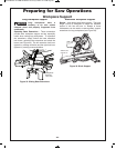
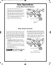
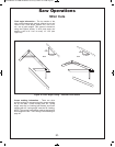
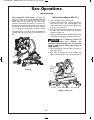
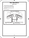
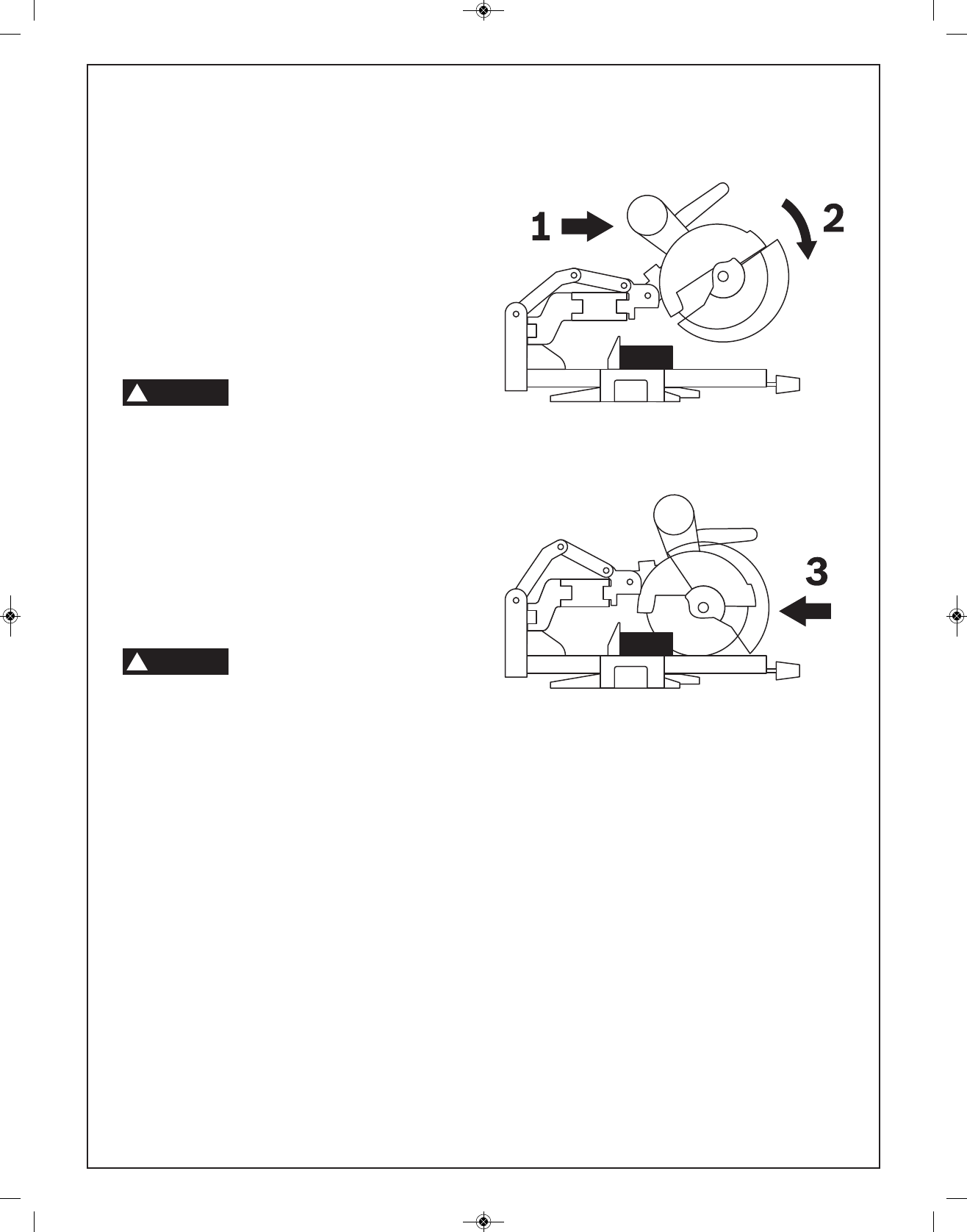
!.86;4.&9612BA
1. Grasp the switch handle and pull the saw head
assembly (in UP position) away from the fence –
see Arrow 1 in Figure 43.
2. Activate the switch, and then fully lower the saw
head assembly – on larger pieces, this action may
also start the cut – see Arrow 2 in Figure 43.
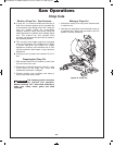
3. Push down and back so the saw head assembly
moves toward the fence and to the full rear
position until you complete the cut. See Arrow 3 in
Figure 43. NOTE: If high resistance is felt, do not
apply excessive force – stop cutting, wait until
blade stops and investigate problem.
4. Hold the saw head down until the blade comes to
a complete stop. Return the saw head to the UP
position and remove the workpiece.
64B?2&9612BA
*%""
!
*%""
!
Saw Operations
&9612BA@
BM 2610007877 04-10:BM 2610007877 04-10.qxp 4/26/10 8:13 AM Page 35