Adjustments
52086;42C29 <08'2;@6<;
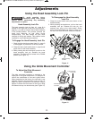
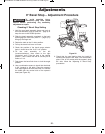
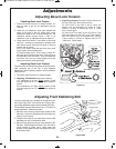
1. Pull up the bevel lock lever to release tension. If it
feels too hard to pull up, an adjustment may be
r
equired.
2. Check the tilt resistance. Grab main handle and
slowly tilt the saw to the left. While tilting, some
resistance should be felt. At approximately 30°, the
resistance should become lower. If little or no
resistance is felt, an adjustment may be required.
3. Check bevel lock tension. Push down on the bevel
lock lever – normally more pressure is needed at the
start; then the lever should go fully down to the lock
position with a “thump”.
A) If it is too hard to push the lever fully down, then
it may require tension adjustment.
B) Check locking power: Tilt the saw to about 30°
and push down on bevel lock lever. Firmly press on
the right side of the saw head - If the saw head tilts
more than 1/2° from the locked position, then the
bevel lock tension needs adjustment.
17B@A6;42C29 <08'2;@6<;
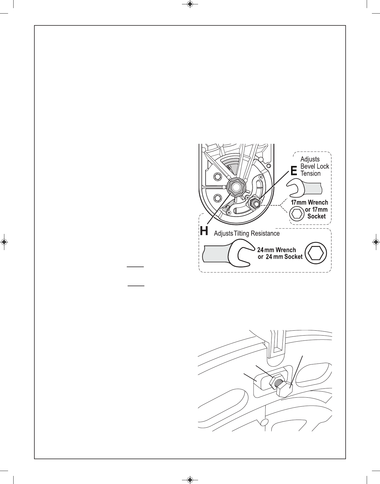
The bevel lock lever tension has been set at the factory.
After extensive use of the tool, it may requirean
adjustment. Before adjusting tension, the tilt resistance
should be set.
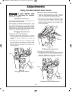
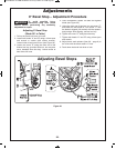
1. Pull up the bevel lock lever to release tension.
2. 17B@A6;4'69A%2@6@A.;02 (see step 2 above).
A) If resistance is too low, slightly tighten (1/16th
turn) the large lock nut “H” using a 24mm socket or
wrench.
B) If resistance is too high, slightly loosen (1/16th
turn) the large lock nut “H” using a 24mm socket or
wrench.
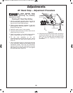
3. 17B@A6;4'2;@6<;(see steps 1 and 3 above) Pull
up and push down the bevel lock lever.
A) If the lever is too hard to pull or push, the
tension can be decreased by using a 17mm
s
ocket or wrench to loosen lock nut “E” (1/8th
turn). Check again.
B) If the lever is too easy to pull or push or if the
saw head does not fully lock at a bevel setting,
then the tension can be increased by using a
17mm socket or wrench to tighten lock nut “E”
(1/8th turn). Check again.
64B?2
17B@A6;42C29 <08'2;@6<;
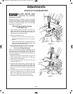
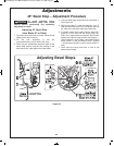
The front stabilizing bolt is located on the bottom of the
saw’s base near the 0° miter detent slot (Figure 26a).
It provides additional support when making slide cuts.
The stabilizing bolt has been factory set. If it is loose or
needs adjustment, follow these steps:
1. Move the saw so that you have easy access to the
bolt area. Loosen the stabilizing bolt and the jam nut
using a 10mm wrench.
2. Place the saw back on your work table. Unscrew the
stabilizing nut until it contacts the table.
3. Move the saw again so that you have access to the
bolt area. While holding the head of the bolt with a
10mm wrench or pliers, use a 10mm open end
wrench to fully tighten the jam nut against the boss
in the saw’s base.
Boss
Jam Nut
Stabilizing Bolt
Adjusting Front Stabilizing Bolt
64B?2.
BM 2610007877 04-10:BM 2610007877 04-10.qxp 4/26/10 8:13 AM Page 25


