


Emerson Process Management GmbH & Co. OHG1-2
X-STREAM XEFD
Instruction Manual
HASXEDE-IM-EX
03/2012
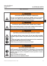
1.3 Protective Measures in Detail
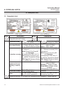
The cast aluminum enclosure consists of two
parts: base and cover, connected by hinges.
The area where the two parts are in contact
is designed to work as a ange, quenching
ames entering the small path between them.
When operated, the analyzer enclosure has to
be closed and secured by 20 screws evenly
arranged all over the ange. The ame path
between the ange parts is manufactured
with very low tolerances and best atness,
to ensure the function of quenching ames.
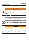
For this reason, it is of particular importance
to keep the anges surfaces free of scratches
and other damages!
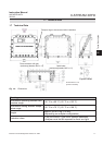
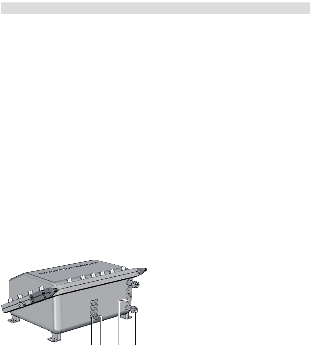
The only openings penetrating the enclosure
are threads, to be used for gas and cable in-
and outlets:
Depending on the measurement application
the instrument provides up to 8 gas in- and
outlets, each protected by an approved ame
arrestor. These arrestors are installed into
threads at the bottom side of the enclosure
base. Two tting sizes are available for ex-
ternal connection of gas pipes with 3.18 mm
(
1
⁄8") or 6.35 mm (
1
⁄4") outer diameter (OD).
Optionally a clamping ring for 6 mm OD may
be used, replacing the 6.35 mm version.
Cables are fed into the enclosure utilizing up
to 4 cable glands, located at the enclosure`s
bottom right side. The approved glands ac-
cept 3 different internal elastomeric sealing
rings with different internal diameters, sup-
porting a wide range of cables.
For installation in North America cable glands
are replaced by a combination of conduits and
metric-to-NPT thread adapters.
All threads are designed to act as a ame
path of a length ensuring that possibly
entering flames are quenched before
exiting to the external atmosphere. For
this reason, avoid to damage the threads,
neither externally nor internally!
Unused threads must be closed with plugs
when the instrument is operated to ensure
explosion protection.
Note!
See the X-STREAM series instruction ma-
nuals for more information about common
gas analyzers features, and special features
of the X-STREAM XEFD.
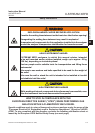
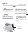
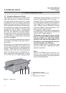
Fig. 1-2: Bottom View
1: Plugged when not used
2: Gas tting (part of ame arrestor)
3: Plug
4: Cable gland (or conduits)
1 2 3 4
1.3 Protective Measures in Detail