


Emerson Process Management GmbH & Co. OHG 2-5
2
Installation
X-STREAM XEFD
Instruction Manual
HASXEDE-IM-EX
03/2012
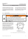
2.3 Installation - Gas Lines
Gas ttings are accessible at the instrument‘s
outer bottom side.The number and assign-
ment of gas inlet and outlet ttings depends
on the application and is given on a label at-
tached to the analyzer‘s bottom side adjacent
to the ttings.
For simple installation we recommend to
mark the gas lines according to the marking
on the analyzer label. This avoids confusion
during re-installation if the analyzer had to be
disconnected for whatever reason.
2.3.1 Special Conditions
The purge medium must be supplied via a
separate ame arrestor (purge gas inlet),
installed into the analyzer enclosure. Another
ame arrestor must be installed, operating as
a breathing device (purge gas outlet).
Connection of breathing device:
The external output of the breathing device
(exhaust) can be open to the ambience of the
analyzer, if inert gas is used as purge medium.
If air is used, the output must end in a safe
area, if the measured gas concentration is
above
25 % V/V LEL.
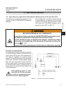
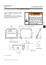
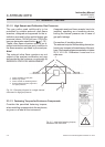
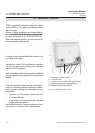
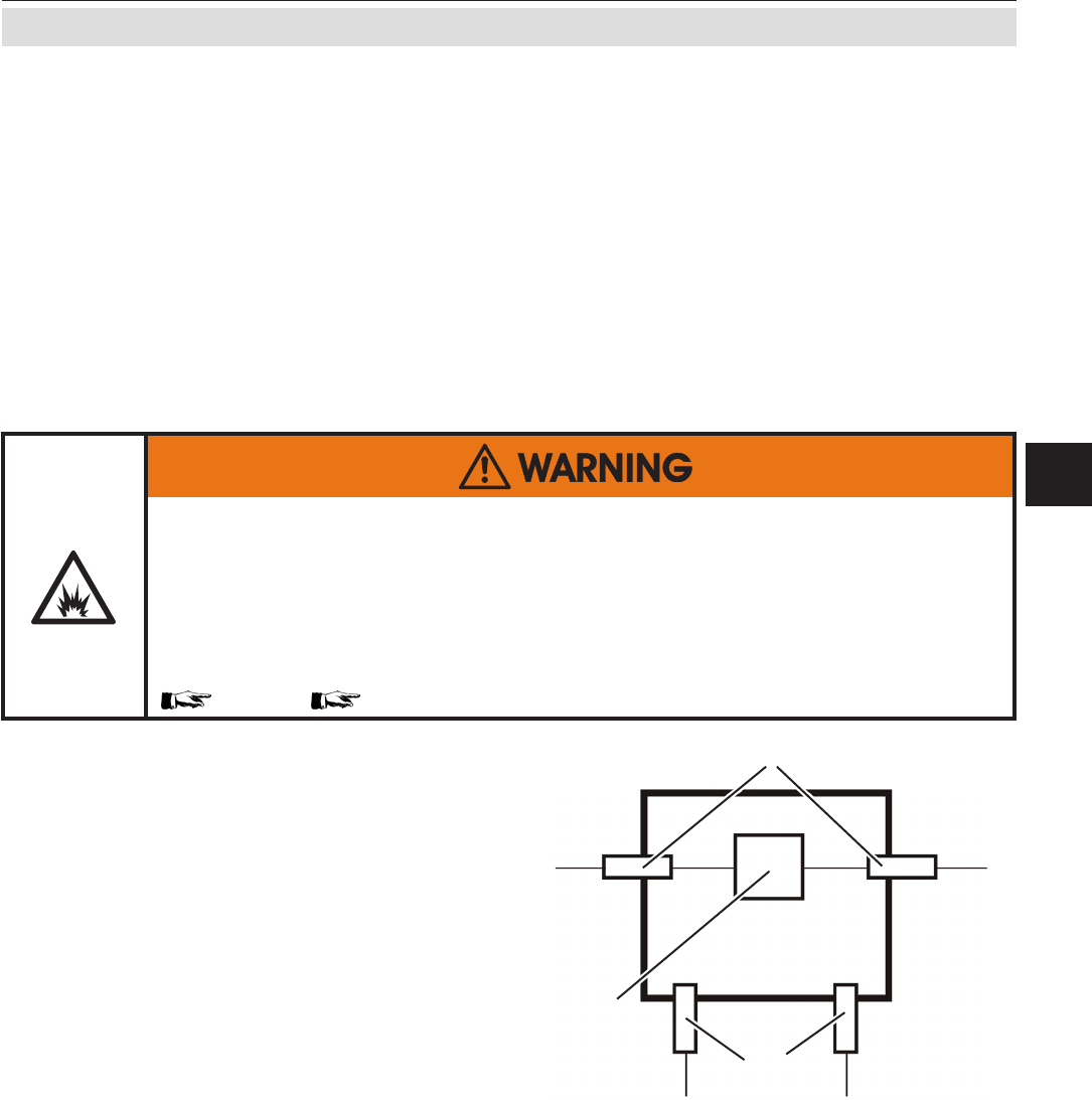
2.3.1.1 Purging the Housing with Clean Gas when e.g. Measuring Low Concentrations
Fig. 2-5: Exemplary diagram for a single channel unit with purge option
1
2
3
1: Flame arrestors for gas path
2: Measuring system
3: Flame arrestors for purge gas in-/outlet
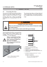
EXPLOSION HAZARD BY HIGH PRESSURE
Risk of internal overpressure under leakage conditions!
For the following option, take care to limit the total of purge gas ow and
highest ow of sample gas lines into the instrument to max. 2 l/min!
Take care of special conditions for safe use, and gas parameter specications
( S-5 and 1-12)!